


9. ALARM PROGRAMMING INFORMATION
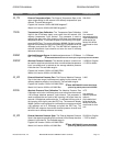
9.1 Alarm ‘ENABLE’ Word Def i ni tion
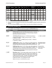
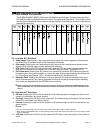
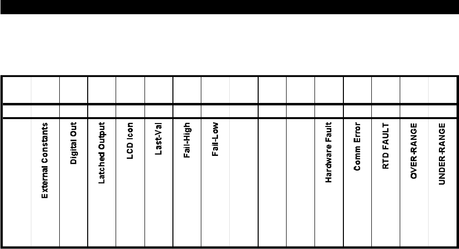
The ALARM ‘ENABLE’ WORD (16 bit word) is divided into two 8 bit bytes. The lower order byte (bits 1 –
8) is used to enable and disable the alarm functions. The higher order byte (bits 9 – 16) is used to control
how the alarm is displayed and/or output to the user interface. Some bits are currently undefined and
reserved for future use.
BIT
16
BIT
15
BIT
14
BIT
13
BIT
12
BIT
11
BIT
10
BIT
9
BIT
8
BIT
7
BIT
6
BIT
5
BIT
4
BIT
3
BIT
2
BIT
1
32768 16384 8192 4096 2048 1024 512 256 128 64 32 16 8 4 2 1
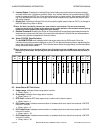
9.2 Low Byte ‘BIT’ Def i ni tions
A. Under-range: En abling the un der-range alarm bit will cause the un der-range alarm to be come ac -
tive when the 4-20 milliamp out put cur rent reaches 3.9 milliamps.
B. Over-range: Enabling the over-range alarm bit will cause the over-range alarm to become active
when the 4-20 milliamp output current reaches 20.5 milliamps.
C. RTD Fault: Enabling the RTD fault alarm bit will cause the RTD fault alarm to become active if an
open circuit or short circuit is sensed in the 4-wire RTD loop connection. See Sec tion 9.3 G
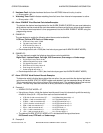
D. ISO Comm er ror: En abling the ISO Comm er ror alarm bit will cause the ISO Comm er ror alarm(s)
to be come ac tive if any com mu ni ca tion er rors or hard ware faults are de tected from any of the ex ter -
nal 4-20 milliamp in put boards. (ISO = Iso lated Out put Mod ule). See Sec tion 9.3 G.
E. Hardware Fault: Enabling the Hardware Fault error alarm bit will cause the Hardware Fault error
alarm to become active if any internal hardware circuit faults (including microprocessor watchdog
timer faults) are detected from the MST2000 internal circuitry.
þNote: For each alarm fault bit above, in di vid ual alarm sta tus bit(s) are pro vided in the ALARM STATUS word to
iden tify which alarm is ac tive. Each alarm sta tus bit and the as so ci ated bi nary val ues are de scribed later in this
sec tion.
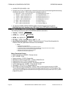
9.3 High Byte ‘BIT’ Def i ni tions
A. Fail-low: Enabling the Fail-low bit will cause the 4-20 milliamp output to change to the fault current
value of 3.8 milliamps if any alarm is active.
B. Fail-high: Enabling the Fail-high bit will cause the 4-20 milliamp output to change to the fault current
value of 21.0 milliamps if any alarm is active.
C. Last-val: Enabling the Last-val bit will cause the 4-20 milliamp output to hold at the last value if any
alarm is active.
þNote:
& The user must insure that only one of the 3 fault current control bits is set for proper operation.
& When entering PROGRAM mode, the 4-20 milliamp output current will change to the fault current as set by the fault
current control bits.
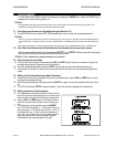
D. LCD Icon: Enabling the LCD Icon bit will cause the LCD ‘Alarm’ icon to be turned on if any alarm is
active.
OPERATION MANUAL ALARM PROGRAMMING INFORMATION
Brandt Instruments, Inc. MST2000 Multivariable SMARTFLOW
®
Transmitter Page 19