


If the ca ble is lon ger than sev eral me ters, it’s re sis tance and ca pac i tance may be come sig nif i cant in the
HART® RC time-constant lim i ta tion ® x C [ 65 mi cro sec onds). When us ing a sin gle field de vice and a
host with a 250 ohm load and no other sig nif i cant re sis tance, the 65 mi cro sec ond lim i ta t ion would al low
0.26 uF of ca pac i tance for the sys tem. Al lowing 0.01 uF (10,000 pF) for the host and field de vice (each
hav ing a CN=1), the to tal ca ble ca pac i tance could be up to 0.25 uF. How ever, if the ca ble re sis tance
was 110 ohms, the sys tem re sis tance be comes 360 ohms, which then al lows for a to tal per mit t ed ca ble
ca pac i tance of 0.18 uF. This cor re sponds to a nom i nal ca ble length of 900 me ters for a ca ble with a rat -
ing of 200 pF/me ter. If the ca ble needs to be ex tended up ward to wards the max i mum HART
®
ca ble
length of 1500 me ters, a ca ble with a lower ca pac i tance rat ing must be se lected.
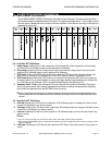
• In a multi-dropped sys tem, the ad di tional ca pac i tance from each net worked trans mit ter must
also be con sid ered. Each trans mit ter has an es tab lished CN value. A CN value of 1 in di cates
that the trans mit ter rep re sents 5000 pF of load ca pac i tance.
• The MST2000 trans mit ter has a CN Value of 1 ( 5000pF).
• The in ter nal re sis tance of the MST2000 trans mit ter is in ex cess of 100,000 ohms and can be ig -
nored in the ca ble length cal cu la tions.
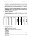
13.4 HART
®
Com mu ni ca tion Dis tance
Up to 1.5 km (1 mile) when using multiple twisted pair cables. Communication distance varies
depending on type of cable used.
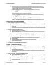
Use the following formula to determine cable length for specific applications:
( )
( )
L
R C
C
C
f
=
×
×
−
+
65 10
10000
6
Where:
L = Length in Meters or Feet
R = Resistance in Ohms (Ω ) including barrier resistance.
C = Cable capacitance in pF/m or pF/ft
C
f
= Maximum shunt capacitance of receiving devices in pF/m or pF/ft.
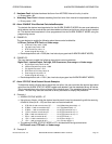
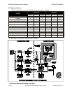
13.5 Power Sup ply Re quire ments
To minimize signal degradation of the HART
®
communication signals, the following power supply
specifications are required.
• Volt age: .......................24 V DC (typ i cal)
• Max i mum rip ple (47 to 125 Hz): ..........0.2 V (peak to peak)
• Max i mum noise (500 Hz to 10 kHz): ........1.2 mV
• Max i mum se ries im ped ance (500 Hz to 10 kHz):..10 ohms
OPERATION MANUAL MST2000 HART® Communications Information
Brandt Instruments, Inc. MST2000 Multivariable SMARTFLOW
®
Transmitter Page 27
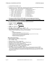
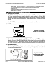
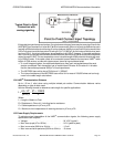
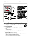
Typical Point to Point
Connection with
analog signaling.