


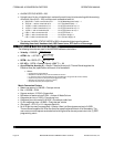

Align the HART
®
mod ule such that con nec tor will be on the bot tom of the board. Snap the mod ule
into the stand offs while mak ing sure the con nec tor and header are prop erly aligned.
g. Re place the cover.
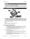
h. Hook up the MST2000 as per the ter mi nal block wir ing di a gram on page 7.
i. Ap ply Power to the MST2000.
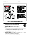
13. MST2000 HART® Communications Information
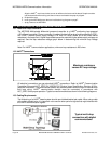
13.1 Power and Loop Con di tions
The MST2000 Multivariable differential pressure transmitter is a HART
®
conforming loop-powered
4-20 milliamp transmitter. Power connection is made at the two left terminal positions marked LOOP+
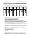
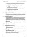
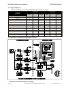
and LOOP-. Nominal power supply voltage is 24 volts DC which allows up to 600 ohms series
resistance in the loop circuit. Higher loop resistance can be used with higher power supply voltages as
required. See the loop resistance-voltage graph below in determining the minimum loop voltage
required.
Note: For HART
®
communication applications, minimum loop resistance is 250 ohms.
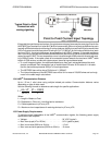
13.2 HART
®
Con nec tions
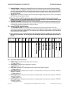
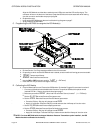
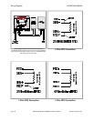
All electrical connections are per standard HART
®
connections. Refer to HART
®
Communication
Foundation Document HCF_SPEC-54 (HART® FSK Physical Layer Specification, Revision 8.0) for
additional information. The current sense resistor may be connected in either the high or low side of the
field loop wiring. HART
®
communication devices must be connected in accordance with
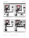
HCF_SPEC-54 for proper operation. Typical connection methods are shown in the following diagrams.
13.3 Ca bling Re quire ments
The field wiring of a HART
®
based system should use shielded twisted pair cable. When using cable
with multiple twisted pairs, it is important not to use the other pairs for signals that might interfere with
the HART
®
communication signals.
MST2000 HART® Communications Information OPERATION MANUAL
Page 26 MST2000 Multivariable SMARTFLOW
®
Transmitter Brandt Instruments, Inc.
Maximum resistance
versus DC loop voltage
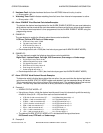
Typical multi-drop
connection with digital
communications.