


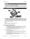
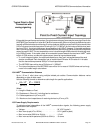
TEST JACK
A Test Jack is stan dard on the Non I.S. Ap proved MST2000’s. It al lows the user to mon i tor the mA out -
put of the unit with out dis con nect ing the loop. Re view di men sional draw ings on page 4. The Test Jack
is re moved for all I.S. and Di vi sion 2 ap proved MST2000’s.
To monitor the mA output of the MST2000 you will need a precision milliammeter. Push the positive l ead
from the meter into the positive jack (RED) and the negative lead from the meter into the negative jack
(BLACK).
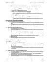
12. OPTIONAL MODULE INSTALLATION
The MST2000 Loop Powered Multivariable SMARTFLOW
®
Trans mit ter’s de sign is such that op -
tional in put, dig i tal I/O and HART
®
com mu ni ca tion mod ules can be in stalled in the field. This al lows the
user the ver sa til ity to change and adapt to dif fer ent ap pli ca tion needs. This sec tion con tains guide lines
for in stall ing the op tional mod ules and up dat ing the MST2000’s pro gram ming if nec es sary. Please re -
view this sec tion be fore at tempt ing to make any up grades. If there are any ques tions or prob lems
please call the fac tory for as sis tance.
þNOTE:
& Any upgrades should be made in a clean and dust free environment.
& Anti-static discharge precautions should be adhered to.
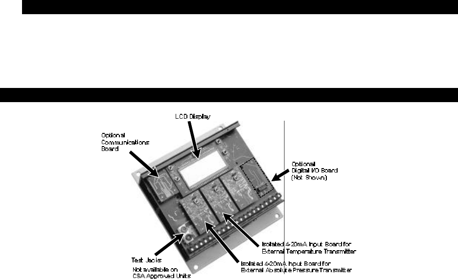
12.1 Iso lated 4-20mA In put Mod ules (ISO Mod ule)
A. Thermo Brandt Part Number FP37-OPTN-ISO
a. The Iso lated 4-20mA In put Mod ule (ISO) al lows the MST2000 to ac cept an iso lated 4-20mA sig nal
from ei ther an Ab so lute Pres sure Trans mit ter or Ex ter nal Tem per a ture Trans mit ter. The 2nd D.P.
Trans mit ter Op tion is un avail able at the time this man ual was printed.
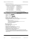
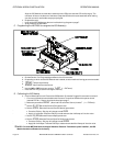
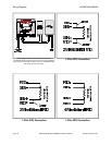
b. All iso lated 4-20mA In put Mod ules are iden ti cal, but they must be mounted in the cor rect lo c a tion on
the Main Board. See pho to graph and draw ings in this sec tion.
c. The Mod ule will be shipped in a sealed bag along with stand offs (2) and in struc tion sheet.
B. Installing the ISO Module Option.
a. Dis con nect all power from the MST2000.
b. De cide which slot the ISO Mod ule will fill. Re move the Op tion Cover La bel cov er ing that slot.
c. Take off the MST2000 Cover by re mov ing the 4 flat head screws. It is not nec es sary to re move the
Main Board from the hous ing.
d. Lo cate the slot, con nec tor and two mount ing holes for the ISO Mod ule on the Main Board.
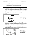
e. Re move the ISO Mod ule and two (2) stand offs from the bag.
f. Snap the Stand offs into the two holes lo cated on the Main Board as shown in the draw ing. Note the
ori en ta tion of the stand off.
g.
OPERATION MANUAL TEST JACK
Brandt Instruments, Inc. MST2000 Multivariable SMARTFLOW
®
Transmitter Page 23