


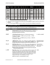

Pa ram e ter De scrip tion Fac tory De fault
OUTPTG Output Gain. The Output Gain parameter allows the user to adjust the
actual 20 milliamp (span) output value as referenced to the MST2000
displayed full scale value. The output gain parameter is displayed and
stored in memory as a gain multiplier. After the EDIT key is pressed, the
edit menu displays the actual multiplier value and the microprocessor
sets the output to the 20.000 milliamp value. The user then uses the
INC and DEC keys to adjust the desired full scale milliamps. Use the
MODE key to adjust the cursor position (i.e., x D1, x D01, x D001 etc.)
to change the gain multiplier in different increments. The available
range is 0.8000 to 1.1000. (Approximately 16.5 to 20.5 milliamp
adjustment range). The factory default is as set by the factory during
initial system calibration.
This is a factory
default setting
determined during
calibration. It should
be recorded by the
user in the event it
will be necessary to
restore the Output
Gain to the original
value. This setting
is also recorded on a
label located under
the cover of the
MST2000.
þNOTE: The minimum and maximum output current range is 3.9 milliamps
and 20.5 milliamps (3.8 milliamps is reserved for fault ‘low’ current and
21.0 milliamps is reserved for fault ‘high’ current).
þNote: If HART
®
com mu ni ca tions are en abled, the min i mum cur rent is lim -
ited to 4.0 milliamps.
AVGFAC Averaging Factor. The Averaging Factor controls the digital filtering
level (damping) of the displayed pressure value (and the 4-20 milliamp
output). The average factor parameter controls the size (depth) of the
digital FILO (first in – last out) filter algorithm. Available range is 1 to 10.
The average factor does not affect the inherent update rate of the LCD
or 4-20 milliamp output (approximately two times per second) except
during power up initialization when the FILO registers are first being
loaded.
1= No Filtering
DEFDSP Default Display. The Default Display parameter assignment selects
the LCD display mode after power up and initialization. Available
assignments are:
0 = INWC for
English.
0 = MMWC for
Metric.
Eng lish Unit Ver sion: 0 = INWC (pri mary vari able), 1 = SCFM, 2 = ACFM,
3 = LBHR or 4 = SCAN. Se lecting SCAN will cause the dis play to se quence
through the cal cu lated vari ables at 4 sec ond in ter vals.
Met ric Unit Ver sion: 0 = MMWC (pri mary vari able), 1 = NM3-HR, 2 =
M3-HR, 3 = KG-HR or 4 = SCAN. Se lecting SCAN will cause the dis play to
se quence through the cal cu lated vari ables at 4 sec ond in ter vals.
DSPRES Display Resolution. The Display Resolution parameter assignment
controls the number of digits that are displayed to the right of the
decimal. The display resolution can be set as fol lows:
3 = X.XXX
Eng lish Unit Ver sion: From 1 to 4 Digits to the right of the dec i mal. Met ric
Unit Ver sion: From 1 to 3 Digits to the right of the dec i mal.
aLARMS The MST2000 has multiple alarm features. Alarms are available for
4-20 milliamp limit checks (under-range and over-range), RTD faults,
external 4-20 milliamp PCB communication failures and internal
hardware circuit faults. Alarms are enabled and disabled by setting the
individual binary bits in the ALARM WORD register to a ‘1’ or ‘0’
respectively. Since the individual binary bits cannot be displayed on the
LCD, the user must input the decimal word equivalent representing the
enabled and disabled bits. The individual alarm bit assignments and
the associated binary values are shown in Sec tion 9.
0 = Alarms Disabled
OPERATION MANUAL PROGRAM PARAMETERS
Brandt Instruments, Inc. MST2000 Multivariable SMARTFLOW
®
Transmitter Page 17