


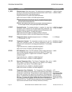
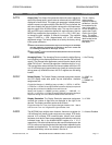
G. Hardware Fault: Indicates hardware fault error from MST2000 internal circuitry is active.
• Bi nary value = 64.
H. Watchdog Timer Fault: Indicates watchdog timer fault error from internal microprocessor is active.
• Bi nary value = 128.
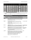
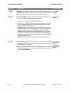
9.6 Alarm ‘ENABLE’ Word Dec i mal Cal cu la tion Ex am ples
To calculate the decimal word equivalent for the ALARM ‘ENABLE’ WORD the user must determine
which alarms and alarm control bits are to be enabled and then sum the binary values of each enabled
bit. The decimal word equivalent is then programmed into the ALARM ‘ENABLE’ WORD using the
programming menus.
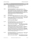
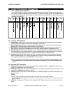
A. EXAMPLE 1
The user desires to enable the following alarm/alarm control enable bits:
LCD Icon, Fail-low, RTD Fault and Under-range.
a. LCD Icon bi nary value = 2048
b. Fail-low bi nary value = 256
c. RTD Fault bi nary value = 4
d. Un der-range bi nary value = 1
• Dec i mal equiv a lent sum = 2309 (dec i mal value to pro gram into ALARM ‘EN ABLE’ WORD).
B. EXAMPLE 2
The user desires to enable the following alarm/alarm control enable bits:
Digital Out1, Latched Output, Fail-high, ISO Comm error, Over-range and Under-range.
a. Dig i tal Out1 bi nary value = 8192
b. Latched Out put bi nary value = 4096
c. Fail-high bi nary value = 512
d. ISO Comm er ror bi nary value = 8
e. Over-range bi nary value = 2
f. Un der-range bi nary value = 1
• Dec i mal equiv a lent sum = 12811 (dec i mal value to pro gram into ALARM ‘EN ABLE’ WORD).
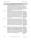
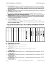
9.7 Alarm ‘STATUS’ Word Dec i mal De code Ex am ples
To determine which individual alarm status bits are active, the user must take the decimal equivalent
value from the ALARM ‘STATUS’ WORD register and decode it into the associated binary bit values.
This is accomplished using binary division of the decimal word. The examples below show manual
division. The user may also use a decimal to binary calculator to simplify this procedure.
A. Example 1
• ALARM ‘STATUS’ WORD = 37
• Using bi nary di vi sion, di vide the dec i mal word by each bi nary bit value start ing with the most sig -
nif i cant bit value (bit 8 = 128) and then each suc ces sive lower bit.
a.
37 B 128 = 0 with a re main der of 37 .......bit 8 (Watch dog timer fault) = 0
b.
37 B 64 = 0 with a re main der of 37 ........bit 7 (Hard ware fault) = 0
c.
37 B 32 = 1 with a re main der of 5 .........bit 6 (ISO comm3 er ror) = 1
d.
5 B 16 = 0 with a re main der of 5 .........bit 5 (ISO comm2 er ror) = 0
e. 5 B 8 = 0 with a re main der of 5 ...........bit 4 (ISO comm1 er ror) = 0
f.
5 B 4 = 1 with a re main der of 1 ...........bit 3 (RTD fault) = 1
g. 1 B 2 = 0 with a re main der of 1 ..........bit 2 (Over-range) = 0
h.
1 B 1 = 1 with a re main der of 0 ...........bit 1 (Un der-range) = 1
• The dec i mal ALARM ‘STATUS’ WORD of 37 in di cates the fol low ing ac tive alarms:
ISO Comm3 error, RTD fault and Under-range.
B. Example 2
OPERATION MANUAL ALARM PROGRAMMING INFORMATION
Brandt Instruments, Inc. MST2000 Multivariable SMARTFLOW
®
Transmitter Page 21