


15
EN
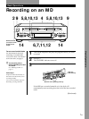
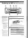
Recording on MDs
Useful Tips for Recording
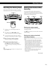
Checking the remaining recordable time on
the MD
Press A TIME/CHAR or B TIME/CHAR.
• When you press the button repeatedly while the
deck is stopped, the display alternates between total
disc playing time and remaining recordable time on
the MD (see page 23).
• When you press the button repeatedly while
recording, the display alternates between the
recording time of the current track and the
remaining recordable time on the MD.
Checking the remaining recordable time with the
remote Z
Press DECK A or DECK B to select the deck, then press
TIME.
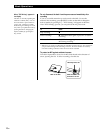
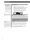
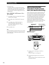
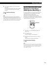
Monitoring the input signal (Input Monitor)
Before starting recording, you can monitor the selected
input signal through the deck’s output connectors.
You can monitor the input signal of deck A or deck B
respectively.
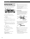
1 Press § EJECT to remove the MD.
2 Press A-INPUT or B-INPUT to select the input
signal you want to monitor on each deck.
When an analog input (ANLG, ANLG A-MD or
ANLG B-MD) is selected
The analog signal input to deck A or deck B is
output to the DIGITAL OPTICAL OUT connector
after A/D conversion, and then to the LINE
(ANALOG) OUT jacks and the PHONES jack after
D/A conversion.
When a digital input (OPT1, OPT2, COAX, A-MD
or B-MD) is selected
After passing through the Sampling Rate
Converter (SRC), the digital signal input to deck A
or deck B is output to the DIGITAL OPTICAL
OUT connector, and after D/A conversion to the
LINE (ANALOG) OUT jacks and PHONES jack.
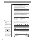
Set A-INPUT and B-INPUT to the combinations
marked with “®” in the table below. If a
combination marked with “—” is selected, you
cannot monitor the input signal.
Selectable input signal combinations
B-INPUT
ANLG OPT1 OPT2
ANLG
A-MD COAX
A-INPUT A-MD
ANLG — ®®—®®
OPT1 ®®®®®®
OPT2 ®®®®®®
ANLG
— ®®——®
B-MD
B-MD ®®®——®
COAX ®®®®®®
® : possible
— : impossible
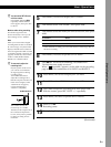
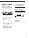
3 Press r REC for the deck to be monitored.
When the analog signal is input to the deck, the
following display appears:
When the digital signal is input to the deck, the
following display appears:
SRC = Sampling Rate Converter
4 Press OUTPUT to turn on the A OUTPUT or
B OUTPUT indicator.
You can monitor the input signal of the deck with
the lighted indicator.
(Continued)
Only when the deck shows detail screen for
deck A or B (see page 23), the selected
digital input appears.
Only when the deck shows detail screen for
deck A or B (see page 23), the selected
analog input appears.
≠ AMS ±
p
0
)
r
·
§
EJECT
P
§
EJECT
≠ AMS ±
p
0
)
r
·
P
≠ AMS ±
≠ AMS ±
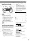
MENU/NO
MENU/NO
A-INPUT
A TIME/CHAR
B TIME/CHAR
B-INPUT
r REC
§ EJECT § EJECT
·
·
p
p
r REC
OUTPUT