


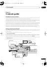

Connecting your equipment
03
16
En
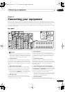
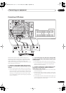
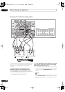
8 Digital audio optical inputs
Two optical digital audio inputs for connecting digital
audio sources to this receiver. All the inputs are freely
assignable to input functions for maximum flexibility.
• If a connected component does not correspond to
the input function (
DVD/LD
, etc.), see
Assigning the
digital inputs
on page 81 to assign it properly.
9 Digital audio outputs
Two optical digital audio outputs for connecting to a CD-
R, MD or other digital recorder. See
Connecting digital
audio sources
on page 25 for connection details.
10 Multi-room and source outputs
The analog audio outputs are for connection to a second
amplifier in a separate room. The
MULTI-ROOM &
SOURCE
composite video output is for connection to a
second monitor or TV in a separate room. See
Multi-room
listening
on page 73.
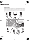
11 Audio/video source inputs
Each of the six source input functions has stereo analog
audio jacks, a composite video jack and an S-video jack
for basic connections. On top of these, you can assign
digital audio and component video jacks to input
functions as necessary. As well as audio/video inputs,
the two input functions
VCR 1/DVR
and
VCR 2
also have
audio/video outputs for recording. See
Connecting a VCR
or DVD recorder
on page 22 for connection details.
12 Monitor video outputs
Two video outputs consisting of a standard composite
video output and an S-video output, for connection to
monitors and TVs. See
Connecting your TV
on page 18 for
connection details.
13 Multichannel pre-amplifier outputs
Multichannel pre-amp outputs that you can use to
connect separate amplifiers for center, surround,
surround back and subwoofer channels. See
Connecting
additional amplifiers
on page 75 for connection details.
14 Multichannel analog audio inputs
7.1 channel analog inputs for connection to a component
with multichannel analog outputs. See
Connecting the
multichannel analog outputs
on page 20 for connection
details.
15 Component video inputs/output
The two component video inputs are freely assignable to
any of the audio/video input functions. The component
video output is for connection to a monitor or TV. See
Using the component video jacks
on page 24 for
connection details.
16 12V trigger jack
This terminal outputs DC 12V according to the input
functions (100 mA max.). See
Switching components on
and off using the 12 volt trigger
on page 65 for connection
details.
17 RS-232C connector
This port is provided for connecting a personal computer
for graphical output when using Advanced MCACC.
18 Speaker terminals
These are the main speaker terminals for front, center,
surround and surround back speakers. See
Installing
your speaker system
on page 28 for connection details.
19 Voltage selector switches
(Multi-voltage model
only)
Use these to match the voltage coming into the receiver
with the voltage in your country or region (see page 3 for
more on this).
20 AC power inlet
Connect the supplied power cord here.
21 AC power outlet
Switched 100W max.
(Continental European model only – Excluding UK)
This 230V AC power outlet can be used to power another
component in your setup (up to 100 W). Power to this
outlet is switched off when the receiver is in standby.
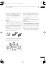
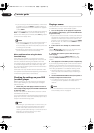
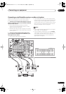
About the video converter
The video converter allows you to connect various video
sources using composite, S-video or component video
connections and the signal will be output through all of
the
MONITOR VIDEO OUT
jacks. The only exception is
component video input, which is only output from the
component video output. Therefore, if you want to
connect any source using component video, you must
also connect your TV using component video. If several
video components are connected to the same input
function, the converter gives priority to component, S-
video, then composite (in that order).
The following chart shows when the video signal will be
converted fro
m the vari
ous video inputs (left column) for
output to the
MONITOR VIDEO OUT
jacks (top row):
• The
mark above indicates that the component
video input must be assigned before it will be output
(see
Assigning the component video inputs
on
page 82 for more on this).
Video
terminal
MONITOR OUT
VIDEO
(Composite)
S-VIDEO
COMPONENT
VIDEO
VIDEO IN
(Composite)
S-VIDEO IN
COMPONENT
VIDEO IN
VSX-AX5Ai.book 16 ページ 2004年6月2日 水曜日 午後3時27分