


63
INSTALLATION AND ASSEMBLY
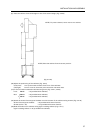
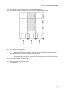
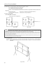
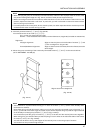
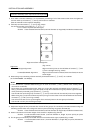
2) Place screen 1 on top of screen 3 of the assembly (in which screens 3 and 4 are already horizontally
connected) and vertically connect (Fig. 3-4-33).
Fix in 2 places (left and right of lower edge)
Screws: Cross-recessed small screws (nominal diameter 4, length 25) (included as accessories)
Alignment
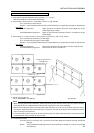
Left/right alignment: Align so that the joint on the right side of screen 1 and the joint on
the right side of screen 3 form a straight line (Fig. 3-4-33).
Forward/backward alignment: Align so that the screen surfaces (wrench surfaces) are at the same
height.
Notes
* Connectors are also required in the corresponding places on the lower edges of the screens in the bottom
row, but if these connectors are attached first then it will not be possible to get the screens to stand up
unsupported, making the subsequent work difficult. These connectors should thus be attached after
mounting the screens on the cabinets.
* If the system setup is such that it will not be possible to attach the lower connectors after mounting the
screens on the cabinets then you should attach these connectors first.
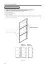
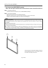
Step 4: Preparing the screens 2 to Mounting on the cabinets
The procedure for this step will be explained separately for the cases of the 4-screen, 6-screen, 9-screen
and 12-screen assemblies.
Notes
* As far as possible you should carry out the work on a level floor, since otherwise it may be difficult to align
the screens correctly.
* Moreover, you should carry out the work as close as possible to the cabinets.
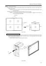
4-screen assembly (work requires at least 2 persons, although 3 persons is better)
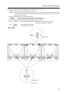
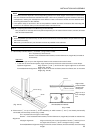
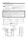
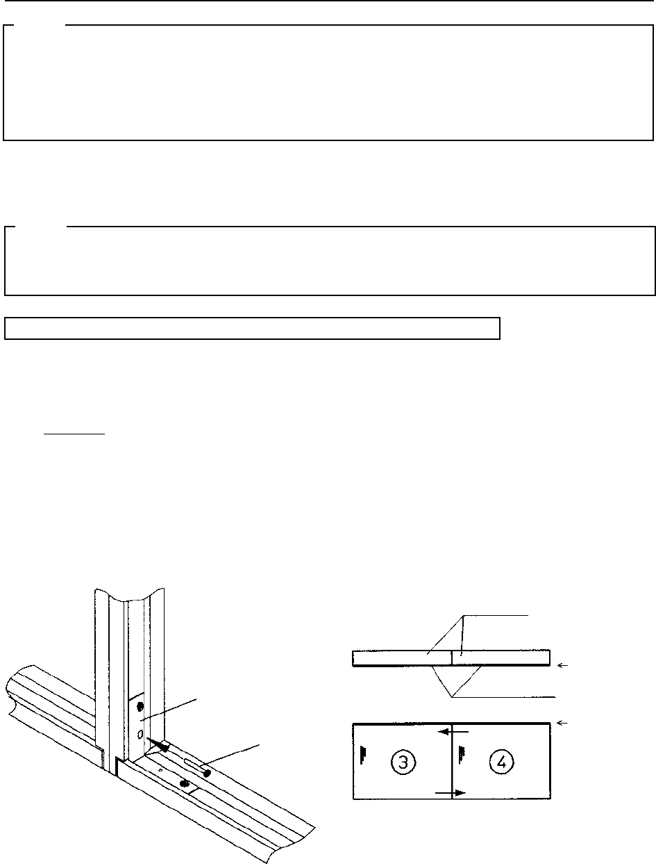
1) Horizontally connect screen 3 to screen 4 (Fig. 3-4-31, 3-4-32).
Fix in 2 places (top and bottom)
Screws: Cross-recessed small screws (nominal diameter 4, length 25) (included as
accessories)
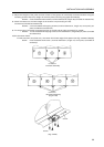
Alignment
* Make sure you carry out the alignment based on the screens and not the frames.
* In the case of the 4-screen system, align the screens such that the center becomes a cross shape.
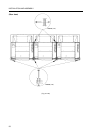
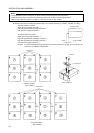
Up/down alignment: Align screens 3 and 4 such that their upper edges are at the same
height (Fig. 3-4-32).
Forward/backward alignment: Align so that the screen surfaces (wrench surfaces) are at the same
height (Fig. 3-4-32).
Corner fitting
Screw
(Fig. 3-4-31)
Frames
Screen surfaces
(Fig. 3-4-32)
(The arrows show the directions in which
the bolts (M4) are inserted)
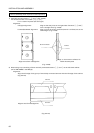
Align so as to
form a straight
line
Align so that
screen surfaces
lie within the
same plane