


59
INSTALLATION AND ASSEMBLY
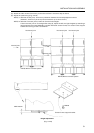
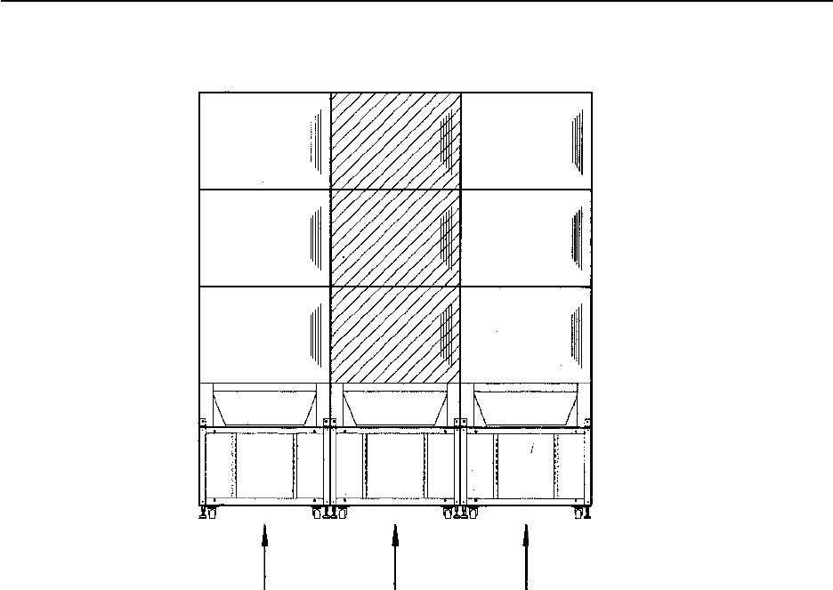
[Fig. 3-4-25]
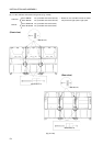
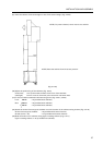
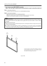
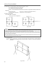
[5] Adjust the positioning. [Fig. 3-4-16]
NOTE) 1. With the vertical joints, remove any clearance between horizontally adjacent screens.
(Note however that there may be gaps of up to 2 mm due to differences in the sizes of parts.)
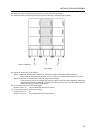
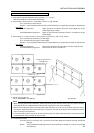
NOTE) 2. With the horizontal joints, make the formed lines straight.
If the horizontal joint is not straight after step [4], adjust the left and right heights by attaching a
height adjustment screw (M6x10, provided with each screen frame) to a screen frame support
bracket and turning it with a screwdriver.
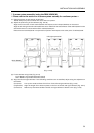
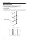
[6] Fix the screen frames (of the lower stage).
Screws: 4 dia. x 12 x 6 (provided with each screen frame)
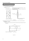
[7] Fix the screen frames (of the upper stage).
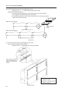
Transport panel V x 2
Screws: 4 dia. x 8 x 4 (provided with each screen frame)
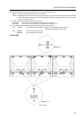
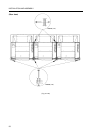
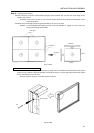
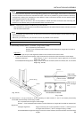
[3] Attach the central 3 screen frame ass’y to the center cabinet. [Fig. 3-4-25]
[4] Attach the other screen frame ass’ies to the other cabinets in the same way as above.
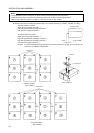
Order of attaching
31 2