


127
ADJUSTMENTS
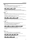
[7] <GST> (GET STATUS) — Various setting states are output.
1 STX (02H)
2 Version of microcomputer software (5 BYTE)
Example)V1.00:Indicates VERSION 1.00.
3 Input function state (3 BYTE)-Output in command name.
Example)IN1:Indicates VIDEO input.
4 MULTI state (3 BYTE)-Output in command name.
Example)MLY:Indicates MULTI=ON.
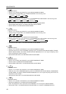
5 COLOR MODE state (3 BYTE)-Output in command name.
Example)CM1:Indicates COLOR MODE=1.
6 COMBINATION state (3 BYTE)-Output in command name.
Example)CMY:Indicates COMBINATION=ON.
7 TV SYSTEM MODE state (3 BYTE)-Output in command name.
(Note 1)
Example)TVA:Indicates TV SYSTEM=AUTO.
8 Indicates the input discriminating result of TV SYSTEM=AUTO
(Note 2)
Example)NTS:Input discriminating result indicates NTSC.
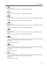
9 Deflection and convergence data memory area state (3 BYTE)
(Note 1)
US1:Indicates that CONV.MEMO-1 is selected.
US2:Indicates that CONV.MEMO-2 is selected.
US3:Indicates that CONV.MEMO-3 is selected.
0 OSD display, enable/disable setting state (3 BYTE)-Output in command name.
Example)DIY:Indicates OSD display enabled.
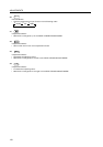
- Setting of function for turning the power on at different times using the ID numbers (on or off, 3
bytes)
DPY: Indicates that the function for turning the power on at different times using the ID num-
bers is on.
DPN:Indicates that the function for turning the power on at different times using the ID num-
bers is off.
= ETX (03H)
(Note 1) When INPUT=VIDEO or Y/C, the VIDEO or Y/C input setting is output.
When INPUT=RGB, the RGB input setting is output.
(Note 2) If it does not TV SYSTEM=AUTO, mode will output the same state of
7
TV SYSTEM.