


11
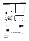
GENERAL SPECIFICATIONS
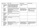
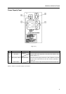
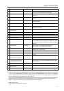
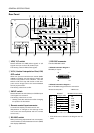
No. Name Type Function
1 ABL linking switch Slide switch When ABL linking is on, the ABL linking control
voltage’s control quantity can be switched
2 Linked input terminal DIN 6-pin ABL, remote control signal and RS-232C signal input
terminal
3 Linked output terminal DIN 6-pin ABL, remote control signal and RS-232C signal output
terminal
4 Remote control connector Mini jack Jack for connecting adjustment remote control unit
(sold separately)
5 RS-232C port D-sub 25-pin RS-232C communications connector
(female)
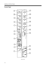
6 Control input terminal BNC connector Video input and Y/C input external switching control
signal input terminal
7 Y (brightness) BNC connector Brightness signal input terminal
input terminal
8 C (color) input terminal BNC connector Color signal input terminal
9 Video input terminal BNC connector Video signal input terminal
0 Video output terminal BNC connector Video input terminal 9 through out terminal
- Terminating switch Slide switch Turn on to terminate video input terminal 9 at 75 ohm
= Input selector switch Tact switch Video input, Y/C input, RGB input selector switch.
At the VIDEO position, switching between the video
input and Y/C input is possible with the external control
signal 6.
~ POWER switch Tact switch When power off: STANDBY (red LED) lights
When power on: ON (green LED) lights
! STATUS indicator switch Tact switch Switch for displaying the total power on time (*), switch
settings, etc., on the screen
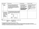
@ RGB input terminal D-sub 9-pin (male) RGB signal input terminal
# RBG input selector switch Slide switch Switch for selecting the RGB signal input terminal
format
$ RGB input terminal BNC connector RGB signal vertical synchronization input terminal
(vertical synchronization)
% RGB input terminal BNC connector RGB signal horizontal synchronization and composite
(horizontal synchronization synchronization (for only input signal H/V synchronization)
/composite synchronization) input terminal
^ RGB input terminal (B) BNC connector RGB signal B input terminal
& RBG input terminal BNC connector RGB signal G or G on Sync input terminal
(G/G on Sync)
* RBG input terminal (R) BNC connector RGB signal R input terminal
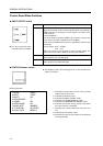
¶ Turn the power off with the POWER switch ~ on the set, through RS-232C control or with the wired remote
control unit (sold separately). (If the power supply is interrupted with the main power switch or if the power
cable is disconnected from the outlet, the switch settings in ! above, the TV system and the convergence
memory settings will not be stored in the last memory.)
Thus, for permanent installations, to start up and stop the entire system by turning the AC power on and off,
the power must first be turned off as described above in order to store the settings in the last memory.
(Refer to “Chapter 4, 2 (5) Last memory of adjustment data and settings “.)
* Total power on time
Only counted when power is set to ON.