


47
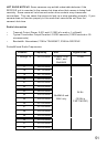
One Unit Equalization
To equalize two cameras and one flash at 1/125 with one MultiMAX, follow these
steps:
1. Set the MultiMAX to RECEIVE mode
2. Measure lag times of cameras as described and record the fastest lag for each
3. Determine which camera is faster and which is slower overall
4. Determine the delay time
a. If the slow camera is more consistent use this formula:
i. Slower Camera’s Fastest Lag Time MINUS Faster Camera’s
Fastest Lag Time MINUS 0.0025 {calculated safety margin}
b. If the fast camera is more consistent use this formula:
i. Slower Camera’s Fastest Lag Time MINUS Faster Camera’s
Fastest Lag Time PLUS 0.0025 {calculated safety margin}
5. Press ~/MENU A A B then enter the calculated delay time from Step 4
6. Attach the slower camera’s motor drive to PORT 1
7. Attach the faster camera’s motor drive to PORT 2
8. Attach the flash to the more consistent (smallest lag time variance) camera
9. Trigger the RECEIVE unit either from the TEST key or from a TRANSMIT unit
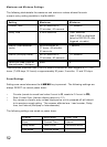
Two Unit Equalization
Two Unit Equalization is basically the same as above, but allows the two cameras to
be more remote. The difference in calculations compensates for radio trigger delay.
1. Set one MultiMAX to RECEIVE mode, and one to TRANSMIT mode
2. Using the RECEIVE unit, measure the lag times of each camera as described
above and record the fastest lag for each
3. Determine which camera is faster and which is slower overall
4. Determine the delay time
1. If the slow camera is more consistent use this formula:
1. Slower Camera’s Fastest Lag Time MINUS Faster Camera’s
Fastest Lag Time MINUS 0.0030 {calculated safety margin}
2. If the fast camera is more consistent use this formula:
1. Slower Camera’s Fastest Lag Time MINUS Faster Camera’s
Fastest Lag Time PLUS 0.0020 {calculated safety margin}
5. On the RECEIVE unit press ~/MENU A A A. Enter the time from Step 4
6. Attach the slower camera’s motor drive to PORT 2 on the TRANSMIT unit. Do
not leave the MultiMAX (set for TRANSMIT mode) in the hot shoe or have the
PC terminal attached to PORT 1 as this may cause a looping or lock-up situation
7. Attach the faster camera’s motor drive to either PORT on the RECEIVE unit
8. Attach the flash to the more consistent (smallest lag time variance) camera
9. Trigger the system from the TRANSMIT unit’s TEST key