


ENGLISH
20
FM
(
75
)
GND AM
DC OUT
OUTPUT
COMPONENT
VIDEO
IN OUT
PRE
OUT
SLL
RSR
FLASHER
IN
INPUT 1
(
DVD
)
COAX.
DIGITAL IN
DIGITAL OUT
3
54
21
SURROUND
BACK
OUT
R
OUT
L
RS-232C
OUTPUT
TAPE CD/CD-R
OUTOUTIN
MULTI
R
L
DSS
(
AUX2
)
AUDIO
TV
7.1CH
IN
IN
OPT.
DVD
(
2
)
DSS
(
4
)
TV
(
1
)
VIDEO
OUT
VCR
(
3
)
OUTIN
RC-5MULTI RC
INPUT 1
(
TV
)
INPUT 4
(
DSS
)
IN
SR
VCR
IN
INPUT 3
(
VCR
)
DVD SL
INPUT 2
(
DSS
)
ANTENNA
C
B
/
P
B
C
R
/
P
R
C
R
/
P
R
C
R
/
P
R
C
B
/
P
B
C
B
/
P
B
Y YY
DVD
(
2
)
DSS
(
4
)
VCR
(
3
)
TV
(
1
)
MONI. OUT
MONITOR
OUT
SBR
SBL
SBR
SBL
C
SW
SW
C
R
L
AC IN
INPUT 2
(
DVD
)
S-VIDEO
MODEL NO. SR6001
O
MULTI SPEAKE
R
/
SPEAKER C
HDMI
Ver1.2
UNSWITCHED
1.25A 150W
SWITCHED
1.25A 150W
AC OUTLETS
120V 60Hz
XM
LR
AUDIO
OUT
DIGITAL
OUT
VIDEO
OUT
S-VIDEO
OUT
S-VIDEO
IN
LR
AUDIO
OUT
AUDIO
IN
LR
VIDEO
OUT IN
S-VIDEO
OUT IN
YC
B
/
P
B
C
R
/
P
R
COMPONENT
VIDEO OUT
YC
B
/
P
B
C
R
/
P
R
COMPONENT
VIDEO IN
L R
L R L R LR
L LR R
FM
(
75
)
GND AM
DC OUT
OUTPUT
COMPONENT
VIDEO
IN OUT
PRE
OUT
SLL
RSR
FLASHER
IN
INPUT 1
(
DVD
)
COAX.
DIGITAL IN
DIGITAL OUT
3
54
21
OUT
R
OUT
L
RS-232
C
OUTPUT
TAPE CD/CD-R
OUTOUTIN
MULTI
R
L
DSS
(
AUX2
)
AUDIO
TV
7.1CH
IN
IN
OPT.
DVD
(
2
)
DSS
(
4
)
TV
(
1
)
VIDEO
OUT
VCR
(
3
)
OUTIN
RC-5MULTI RC
INPUT 1
(
TV
)
INPUT 4
(
DSS
)
IN
SR
VCR
IN
INPUT 3
(
VCR
)
DVD SL
INPUT 2
(
DSS
)
ANTENNA
C
B
/
P
B
C
R
/
P
R
C
R
/
P
R
C
R
/
P
R
C
B
/
P
B
C
B
/
P
B
YYY
DVD
(
2
)
DSS
(
4
)
VCR
(
3
)
TV
(
1
)
MONI. OUT
MONITOR
OUT
SBR
SBL
SBR
SBL
C
SW
SW
C
INPUT 2
(
DVD
)
S-VIDEO
HDMI
Ver1.2
XM
RS-232
C
LR
AUDIO
OUT
DIGITAL
OUT
VIDEO
OUT
S-VIDEO
OUT
AUDIO
OUT
LR
VIDEO
OUT
S-VIDEO
IN
VIDEO
IN
LR
L R
L R
L R
LR
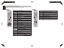
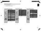
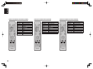
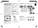
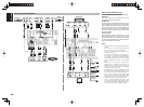
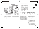
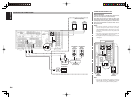
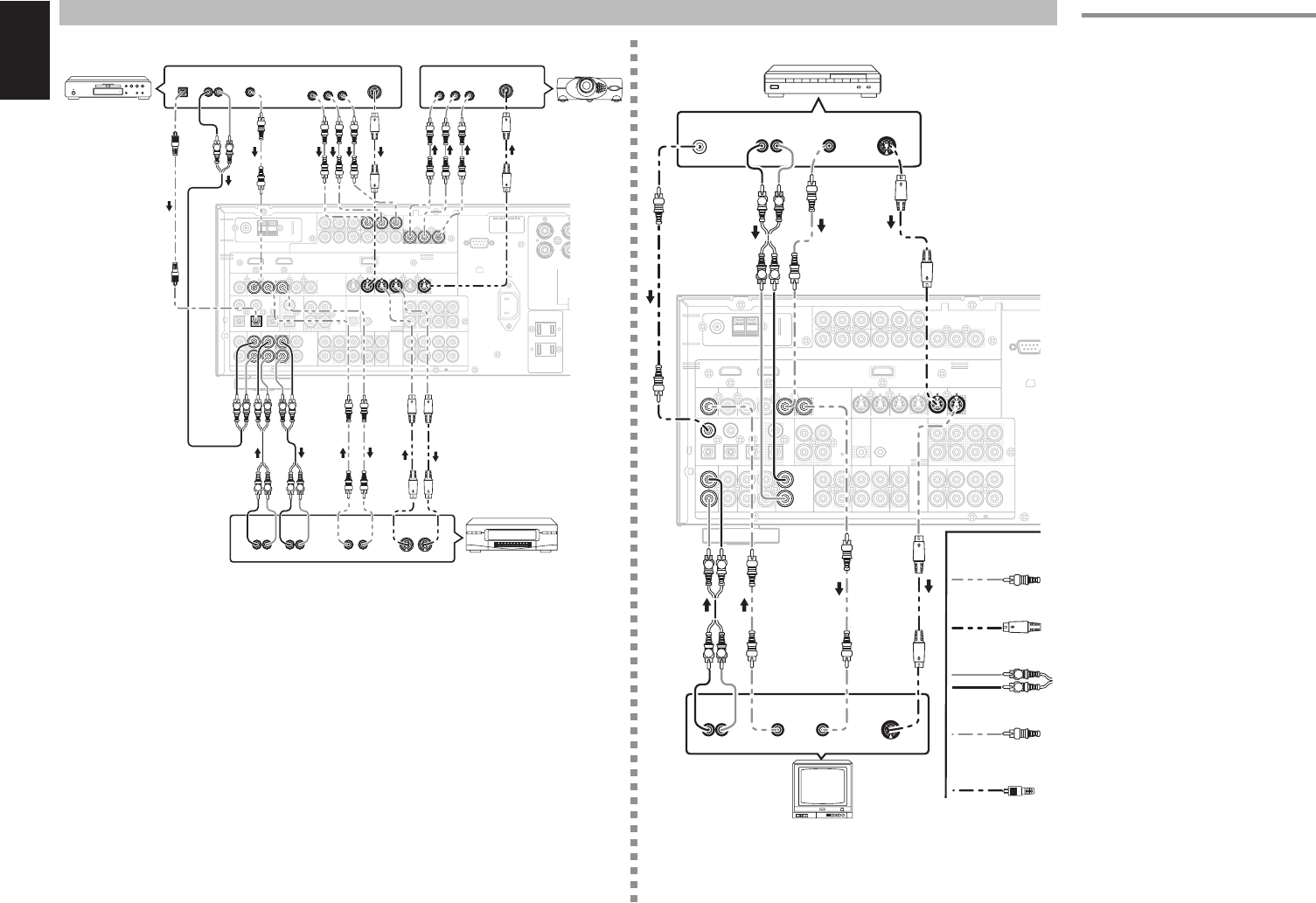
CONNECTING VIDEO COMPONENTS
Analog Audio
Video
S-Video
DVD player
VIDEO
PROJECTOR
Satellite Tuner
Digital Audio
(coaxial)
VCR
TV
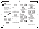
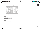
VIDEO, S-VIDEO, COMPONENT JACKS
There are 3 types of video jacks on the rear panel.
VIDEO jack
The video signal for the VIDEO jacks is the
conventional composite video signal.
S-VIDEO jack
The video signal is separated into luminance (Y) and
color (C) signals for the S-VIDEO jack. The S-VIDEO
signals enables high-quality color reproduction. If
your video component has an S-VIDEO output, we
recommend to use it. Connect the S-VIDEO output
jack on your video component to the S-VIDEO input
jack on the SR6001.
Component jack
Make component video connections to a TV or
monitor with component inputs to produce higher
quality video images. Use a component video cable
or 3 video cords to connect the component video out
jacks on the SR6001 to the monitor.
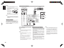
Notes:
•
Be sure to connect the left and right audio channels
properly.
Red connectors are for the R (right) channel, and
white connectors are the for L (left) channel.
• Be sure to connect the inputs and outputs of the
video signals properly.
•
If you connect the S-VIDEO or component signal to
the S-VIDEO or component jack on the SR6001, it is
not necessary to connect the conventional video signal
to the VIDEO (composite) jack. If you use both video
inputs, the SR6001 gives priority to the S-VIDEO
signal.
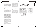
• Each type of video jack works independently.
Signals input to the VIDEO (composite) and S-
VIDEO jacks or component are output to the
corresponding VIDEO (composite) and S-VIDEO
or component jacks, respectively.
•
T
he SR6001
has the “TV-AUTO ON/OFF” function
to turn the TV ON or OFF automatically, by sensing
the incoming video signal from the VIDEO jacks.
• You may need to setup the digital audio output
format of your DVD player, or other digital source
components. Refer to the instructions of the each
component connected to the digital input jacks.
• There is no Dolby Digital RF input jack. Use an
external RF demodulator Dolby Digital decoder
when connecting the Dolby Digital RF output jack
of the videodisc player to the digital input jack.
Digital Audio
(optical)