– 6 –
Getting Started
Continued
Unpacking
After unpacking, check to be sure that you have all the
following items.
The number in the parenthesis indicates the quantity of the
pieces supplied.
• AM loop antenna (1)
• FM antenna (1)
• Remote control (1)
• Batteries (2)
• AC plug adaptor (1)
If any is missing, consult your dealer immediately.
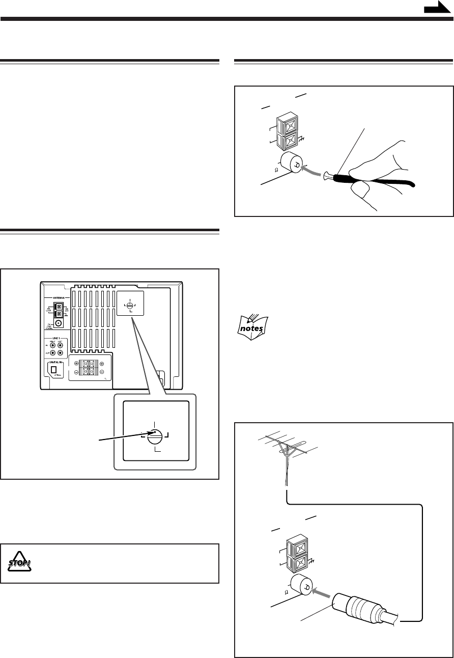
Adjusting the Voltage Selector
Before plugging in the unit, set the correct voltage for your
area with the voltage selector on the rear of the unit.
Use a screwdriver to rotate the voltage selector so the
voltage number the voltage mark is pointing at is the same
as the voltage where you are plugging in the unit.
• DO NOT plug in before setting the voltage
selector on the rear of the unit and all connection
procedures are complete.
Voltage mark
SPEAKER
IMPEDENCE 6
16Ω
CAUTION:
SPEAKERS
RIGHT LEFT
VOLTAGE SELECTOR
230 -
240V
220V
127V
110V
VOLTAGE SELECTOR
230 -
240V
220V
127V
110V
1 Attach the FM antenna to the FM (75 Ω) COAXIAL
terminal.
2 Extend the FM antenna.
3 Fasten it up in the position which gives you the best
reception.
About the supplied FM antenna
The FM antenna supplied with this unit can be used as temporary
measure. If reception is poor, you can connect an outdoor FM
antenna.
To connect an outdoor FM antenna
Before connecting it, disconnect the supplied FM antenna.
FM antenna (supplied)
Outdoor FM antenna
(not supplied)
A 75Ω antenna with coaxial type connector should
be used.
AM
LOOP
AM
EXT
FM
(75 )
COAXIAL
ANTENNA
AM
LOOP
AM
EXT
FM
(75 )
COAXIAL
ANTENNA
Connecting Antennas
FM antenna
EN01-09.CA-MXS6MD[UJ]/f 00.11.10, 11:26 AM6


