


INSTALLATION AND CONNECTIONS 21
ENGLISH
Installation and Connections
System and Power Connections
The AVR 347 is designed for flexible use with
multiroom systems, external control components
and power amplifiers.
Main Room Remote Control Extension
If the receiver is placed behind a solid or smoked
glass cabinet door, the obstruction may prevent
the remote sensor from receiving commands. In
this event, the remote sensor of any
Harman Kardon or other compatible device, not
covered by the door, or an optional remote
sensor may be used. Connect the Remote IR
Output of that device or the output of the
remote sensor to the Remote IR Input jack
V
.
If other components are also prevented from
receiving remote commands, only one sensor is
needed. Simply use this unit’s sensor or a remote
eye by running a connection from the Remote
IR Output jack
U
to the Remote IR Input
jack on Harman Kardon or other compatible
equipment.
Multiroom IR Link
The key to remote room operation is to link the
remote room to the AVR’s location with wire for
an infrared receiver and speakers or an amplifier.
The remote room IR receiver (this can be an
optional IR receiver or any other remotable
Harman Kardon device in the remote room with
IR sensor integrated) should be connected to the
AVR via standard coaxial cable. Connect the
Remote IR Output of the device or of the
optional sensor with the Multiroom IR Input
jack
d
on the AVR’s rear panel.
If other Harman Kardon compatible source
equipment is part of the main room installation,
the Remote IR Output jack
U
on the rear
panel should be connected to the IR IN jack on
that source device. This will enable the remote
room location to control source equipment
functions.
When a remote IR sensor is used to control non-
Harman Kardon source equipment, we recom-
mend that you make a direct connection or use
an optional, external IR “blaster” connected to
the Remote IR Carrier Output Jack
f
. If you
are in doubt as to which IR Output jack to use
for the equipment in your system, contact your
dealer or installer, or the manufacturer’s support
site and ask whether the unit to be controlled
uses “full carrier” or “stripped” carrier IR
commands. When “full carrier commands” are
used, make the connection to the Remote IR
Carrier Output Jack
f
. Otherwise, make the
connection to the Remote IR Output Jack
U
as noted above.
NOTE: All remotely controlled components must
be linked together in a “daisy chain”.Connect
the IR OUT jack of one unit to the IR IN of the
next to establish this chain.
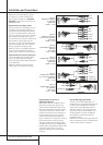
Multiroom Audio Connections
Depending on your system`s requirement and
distance from the AVR to the remote room, three
options are available for audio connection:
Option 1: Use high-quality, shielded audio
interconnect phono cable from the AVR’s loca-
tion to the remote room. In the remote room,
connect the interconnect cable to a stereo
power amplifier.The amplifier will be connected
to the room’s speakers.At the AVR, plug the
audio interconnect cables into the Multiroom
Output Jacks
b
on the AVR’s rear panel.
Option 2: Place the amplifier that will provide
power to the remote location speakers in the
same room as the AVR, and connect the
Multiroom Output jacks
b
on the rear panel
of the AVR to the audio input of the remote
room amplifier. Use the appropriate speaker wire
to connect the optional power amplifier to the
remote speakers. High-quality wire of at least
2.5 mm
2
is recommended for long multiroom
connections.
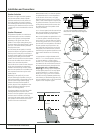
Option 3: Taking advantage of the AVR’s built-
in seven-channel amplifier, it is possible to use
two of the amplifier channels to power speakers
in the remote room.When using this option you
will not be able to use the full 7.1-channel capa-
bilities of the AVR in the main listening room,
but you will be able to add another listening
room without additional external power ampli-
fiers. To use the internal amplifiers to power a
remote zone, connect the speakers for the
remote room location to the Surround
Back/Multiroom Speaker Outputs
O
.
Before using the remote room you will need to
configure the amplifiers for surround operation
by changing a setting in the Multiroom menu,
following the instructions shown on page 47.
NOTE: For all options, you may connect an
optional IR sensor (Harman Kardon He1000) in
the remote room to the AVR via an appropriate
cable. Connect the sensor’s cable to the
Multiroom IR Input
d
on the AVR and use
the Zone II remote to control the room volume.
Alternatively, you may install an optional volume
control between the output of the amplifiers and
the speakers.
NOTE: The AVR 347’s multiroom system is only
capable of distributing analog audio sources to
the remote zone. Therefore, when connecting
your digital audio equipment (e.g. CD or DVD
players) as described on page 17, make sure to
use both analog and digital audio connections
to ensure that the devices will be available to
the multiroom system.
A-BUS Installation Connections
The AVR is among the very few receivers avail-
able today that offers built-in A-BUS Ready
®
operation.When used with an optional A-BUS
keypad or control module, you have all the
benefits of remote zone operation without the
need for an external power amplifier.
To use the AVR with an approved A-BUS prod-
uct, simply connect the keypad or module that is
in the remote room to the AVR using standard
“Category 5” wiring that is properly rated for
the inwall use specific to the installation.
Terminate the wiring at the receiver end to a
standard RJ-45 jack in compliance with the
instructions furnished with the A-BUS module.
You may connect a single A-BUS module to the
AVR 347 with no further equipment needed. If
you wish to connect more than one A-BUS
module, an optional, external A-BUS hub may be
used to provide that capability.
No further installation or adjustment is needed,
as the A-BUS connector on the AVR routes the
signals in and out of the keypad to their proper
destination for power, signal source and control.
The output fed to the A-BUS jack is determined
by the AVR’s multiroom system, and the menus
may be used as is.
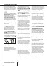
AC Power Connections
This unit is equipped with one accessory AC
outlet. It may be used to power accessory
devices, but should not be used with high-current
draw equipment such as power amplifiers.The
total power draw to the Switched Outlet
G
should not exceed 50 watts.
The Switched
G
outlet will receive power only
when the unit is on completely. This is recom-
mended for devices that have no power switch
or a mechanical power switch that may be left in
the “ON” position.
NOTE: Many audio and video products go into a
Standby mode when they are used with
switched outlets, and cannot be fully turned on
using the outlet alone without a remote control
command.
The AVR draws significantly more current than
other household devices such as computers that
use removable power cords. For that reason, it is
important that only the cord supplied with the
unit (or a direct replacement of identical
capacity) be used.
Once the power cord is connected, you are
almost ready to enjoy the AVR 347’s incredible
power and fidelity!