


REAR PANEL CONNECTIONS 9
ENGLISH
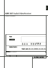
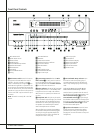
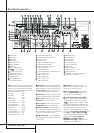
Rear Panel Connections
9
8-Channel Direct Inputs: These jacks are
used for connection to source devices such as
DVD-Audio, Blu-ray, HD-DVD or SACD players
with discrete analog outputs. Depending on the
source device in use, all eight jacks may be used,
though in many cases only connections to the
front left/right, center, surround left/right and
LFE (subwoofer input) jacks will be used for
standard 5.1 audio signals.
A
Digital Audio Outputs: Connect these
jacks to the matching digital input connector on
a digital recorder such as a CD-R or MiniDisc
recorder.
B
Video Monitor Outputs: Connect this jack
to the composite and/or S-Video input of a TV
monitor or video projector to view the on-screen
menus and the output of any standard Video or
S-Video source selected by the receiver’s video
switcher.
C
DVD Video Inputs: Connect these jacks to
the composite or S-Video output jacks on a DVD
player or other video source.
D
Front Speaker Outputs: Connect these
outputs to the matching + or – terminals on
your left and right speakers. In conformance with
the new CEA color code specification, the White
terminal is the positive, or "+" terminal that
should be connected to the red (+) terminal on
Front Left speaker with the older color coding,
while the Red terminal is the positive, or "+"
terminal that should be connected to the red (+)
terminal on Front Right speaker. Connect the
black (–) terminals on the AVR to the black (–)
terminals on the speakers. See page 17 for more
information on speaker polarity.
E
Center Speaker Outputs: Connect these
outputs to the matching + and – terminals on
your center channel speaker. In conformance
with the new CEA color code specification, the
Green Terminal is the positive, or "+" terminal
that should be connected to the red (+) terminal
on speakers with the older color coding. Connect
the black (–) terminal on the AVR to the black
negative (–) terminal on your speaker. (See page
17 for more information on speaker polarity.)
F
Surround Speaker Outputs: Connect
these outputs to the matching + and – terminals
on your surround channel speakers. In confor-
mance with the new CEA color code specifica-
tion, the Blue terminal is the positive, or "+"
terminal that should be connected to the red (+)
terminal on the Surround Left speaker with older
color coding, while the Gray terminal should be
connected to the red (+) terminal on the
Surround Right speaker with the older color
coding. Connect the black (–) terminal on the
AVR to the matching black negative (–)
terminals for each surround speaker. (See page
17 for more information on speaker polarity.)
G
Switched AC Accessory Outlet:This
outlet may be used to power any device that you
wish to have turn on when the AVR is turned on
with the System Power Control switch
2
.
H
RS-232 Serial Port: This specialized
connector may be used with your personal
computer in case Harman Kardon offers a soft-
ware upgrade for the receiver at some time in
the future. Leave the Mode switch popped out in
the Operate position, unless the AVR 347 is
being upgraded.The Reset switch is used only
during the upgrade process.
I
AC Power Cord: Connect the AC plug to an
unswitched AC wall output.
J
Video 2 Component Video Inputs:
Connect the Y/Pr/Pb component video outputs of
an HDTV Set-top convertor, satellite receiver, or
other video source device with component video
outputs to these jacks. The factory default is for
these jacks to be a linked to the Video 1 input,
but you may change the setting at any time
through the
INPUTSETUP menu. See page
24 for more information on configuring the com-
ponent video inputs.
K
Monitor Component Video Outputs:
Connect these outputs to the component video
inputs of a video projector or monitor.When a
source connected to one of the three
Component Video Inputs
JLe
is selected
the signal will be sent to these jacks.
L
Video 1 Component Video Inputs:
Connect the Y/Pr/Pb component video outputs of
a DVD player to these jacks. The factory default
is for these jacks to be a linked to the DVD
input, but you may change the setting at any
time through the
INPUTSETUP menu. See
page 24 for more information on configuring the
component video inputs.
Note: All component inputs/outputs can be
used for RGB signals too, in the same way as
described for the Y/Pr/Pb signals, then connected
to the jacks with the corresponding color.
RGB connection is not possible if the source out-
puts a separate sync signal (see page 18).
M
Video 2 Audio Inputs: Connect these jacks
to the PLAY/OUT audio jacks on a second VCR
or other audio or video source.
N
Coaxial Digital Inputs: Connect the coax
digital output from a DVD player, HDTV receiver,
the output of a compatible computer sound card
playing MP3 files or streams, LD player, MD
player or CD player to these jacks. The signal
may be either a Dolby Digital signal, DTS signal,
a 2 channel MPEG 1 signal, or a standard PCM
digital source. Do not connect the RF digital out-
put of an LD player to these jacks.
O
Surround Back/Multiroom Speaker
Outputs: These speaker terminals are normally
used to power the surround back left/surround
back right speakers in a 7.1 channel system.
However, they may also be used to power the
speakers in a second zone, which will receive the
output selected for a multiroom system.
To change the output fed to these terminals
from the default of the Surround Back speakers
to the Multiroom Output, you must change a
setting in the
MULTIROOMMENUof the
OSD system. See page 47 for more information
on configuring this speaker output. In normal
surround system use, the brown and black termi-
nals are the surround back left channel positive
(+) and negative (–) connections and the tan
and black terminals are the surround back right
positive (+) and negative (–) terminals.
For multiroom use, connect the brown and black
SBL terminals to the red and black connections
on the left remote zone speaker and connect the
tan and black SBR terminals to the red and black
terminals on the right remote zone speaker.
P
Video 1 Video Outputs: Connect these
jacks to the RECORD/INPUT composite or
S-Video jack on a VCR.
Q
Video 1 Video Inputs: Connect these jacks
to the PLAY/OUT composite or S-Video jacks on
a TV or other video source.
R
Optical Digital Inputs: Connect the
optical digital output from a DVD player, HDTV
receiver, the output of a compatible computer
sound card playing MP3 files or streams, LD
player, MD player or CD player to these jacks.
The signal may be either a Dolby Digital signal, a
DTS signal, a 2 channel MPEG 1 signal, or a
standard PCM digital source.
S
Video 1 Audio Inputs: Connect these jacks
to the PLAY/OUT audio jacks on a TV or other
audio or video source.
T
Video 2 Video Inputs: Connect these jacks
to the PLAY/OUT composite or S-Video jacks on
a second VCR or other video source.