


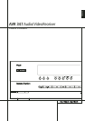
FRONT PANEL CONTROLS 7
ENGLISH
7
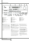
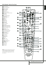
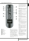
Selector Buttons: When you are establishing
the AVR’s configuration settings, use these buttons
to select from the choices available, as shown in
the Main Information Display
Ò
.
8
Tone Mode: Pressing this button enables or
disables the Balance, Bass and Treble tone
controls. When the button is pressed so that the
words
TONEINappear in the Main
Information Display
Ò
, the settings of the
Bass and Treble controls and of the Balance
control will affect the output signals. When the
button is pressed so that the words
TONE
OUT
appear in the Main Information
Display
Ò
, the output signal will be “flat,”
without any balance, bass or treble alteration.
9
Surround Mode Selector: Press this button
to select from among the available surround
mode options for the mode group selected.The
specific modes will vary based on the number of
speakers available, the mode group and if the
input source is digital or analog. For example,
press the Surround Mode Group Selector
5
to select a mode grouping such as Dolby or Logic
7, and then press this button to see the mode
choices available. For more information on mode
selection, see page 40.
)
Tuning Selector: Press the left side of the
button to tune lower frequency stations and the
right side of the button to tune higher frequency
stations. When a station with a strong signal is
reached,
MANUALTUNED or AUTO
TUNED
will appear in the Main Information
Display
Ò
(see page 51 for more information
on tuning stations).
!
Tuner Band Selector: Pressing this button
will automatically switch the AVR to the Tuner
mode. Pressing it again will switch between the
AM and FM frequency bands, holding it pressed
for some seconds will switch between stereo and
mono receiving and between automatic and
manual tuning mode (See page 51 for more
information on the tuner).
@ Set Button: When making choices during the
setup and configuration process, press this button
to enter the desired setting as shown in the
Main Information Display
Ò
into the AVR’s
memory.
#
Preset Stations Selector: Press this
button to scroll up or down through the list of
stations that have been entered into the preset
memory (See page 51 for more information on
tuner programming).
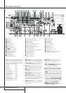
$
Speaker/Channel Input Indicators:These
indicators are multipurpose, indicating either the
speaker type selected for each channel or the
incoming data-signal configuration.The left, center,
right, right surround and left surround speaker
indicators are composed of three boxes, while the
subwoofer is a single box.The center box lights
when a “Small” speaker is selected, and the two
outer boxes light when “Large” speakers are
selected.When none of the boxes are lit for the
center, surround or subwoofer channels, no speaker
has been selected for that position. (See page 31
for more information on configuring speakers.) The
letters inside each of the center boxes display
active input channels. For standard analog inputs,
only the L and R will light, indicating a stereo
input.When a digital source is playing, the indica-
tors will light to display the channels being
received at the digital input.When the letters
flash, the digital input has been interrupted.
(See page 44 for more information on the Channel
Indicators).
NOTE: When you have reassigned the surround
back speakers to the remote zone using the
MULTIROOMSETUPmenu, the boxes that
indicate the presence of the surround back speak-
ers will automatically disappear, reflecting the fact
that the main listening area is now configured for
5.1-channel operation. (See page 47 for more
information on reassigning the surround back
speakers for multiroom use.)
%
Input Source Selector: Press this button to
change the input by scrolling through the list of
input sources.
^
RDS Select Button: Press this button to
display the various messages that are part of the
RDS data system of the AVR’s tuner.
(See page 52 for more information on RDS).
&
Delay: Press this button to begin the
sequence of steps required to enter delay time
settings (See page 34 for more information on
delay times).
*
Digital Optical 4 Input: Connect the
optical digital audio output of an audio or video
product to this jack.When the Input is not in use,
be certain to keep the plastic cap installed to
avoid dust contamination that might degrade
future performance.
(
Surround Mode Indicators: The current
selected mode or function will appear as one of
these indicators. Note that when the unit is
turned on, the entire list of available modes will
light briefly, and then revert to normal operation
with only the active mode indicator illuminated.
Ó
Digital Coax 4 Input: This jack is normally
used for connection to the output of portable
digital audio devices, video game consoles or
other products that have a coax digital jack.
Ô
Video 4 Input Jacks: These audio/video
jacks may be used for temporary connection to
video games or portable audio/video products
such as camcorders and portable audio players.
Input indicators: The current selected
mode or function will appear as one of these
indicators. Note that when the unit is turned on,
the entire list of available modes will light briefly,
and then revert to normal operation with only
the active mode indicator illuminated.
Ò
Main Information Display: This display
delivers messages and status indications to help
you operate the receiver.
Ú
Remote Sensor Window: The sensor
behind this window receives infrared signals from
the remote control.Aim the remote at this area
and do not block or cover it unless an external
remote sensor is installed.
Note: When /DMP has been selected as
the input source, no Input Indicator
will
light.
DMP/THEBRIDGE IS
CONNECTED
will scroll across the Upper
Display Line
Ò
, unless you have retitled the
source name, in which case that name will
appear. See page 24 for more information on
input titling.
Û
Digital Input Selector: When playing a
source that has a digital output, press this button
to select between the Optical
L
and Coaxial
9
Digital inputs. (See pages 24 and 41 for
more information on digital audio).
Ù
Channel Select Button: Press this button
to begin the process of trimming the channel
output levels using an external audio source.
(For more information on output level trim
adjustment, see page 46).
ı
Volume Control: Turn this knob clockwise
to increase the volume, counterclockwise to
decrease the volume. If the AVR is muted,
adjusting volume control will automatically
release the unit from the silenced condition.
Front Panel Controls