


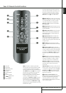

INSTALLATION AND CONNECTIONS 19
ENGLISH
Installation and Connections
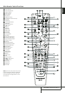
1. Connect a VCR’s audio and video Play/Out
jacks to the Video 2 In jacks
MT
on the rear
panel.The Audio and Video Record/In jacks on
the VCR should be connected to the Video 1
Out jacks
P7
on the AVR.
2.Although any video device may be connected
to these jacks, we recommend connecting your
TV to the Audio 1 Audio/Video Input Jacks
SQ
so that you may take advantage of the
fact that the remote control is preprogrammed
with TV product codes for the Video 1 device.
For the same reason, we recommend connecting
your video recorder, cable TV converter or
satellite receiver to the Video 2 Audio/Video
Input Jacks
MT
.
3. Connect the analog audio and video outputs
of a DVD or laser disc player to the DVD jacks
5C
.
4. Connect the digital audio outputs of a CD,
MD or DVD player, satellite receiver, cable box or
HDTV converter to the appropriate Optical or
Coaxial Digital Inputs
NR*Ó
.
Remember that the DVD source defaults to the
Coaxial 1 Digital Input
N
.All other sources
default to their analog inputs, although any
source may be assigned to any digital audio
input on the receiver.
NOTE: When connecting a device such as a digi-
tal cable box or other set-top tuner product with
a digital audio output, we recommend that you
connect both the digital and analog outputs of
the product to your AVR. The audio input polling
feature of the AVR will then be able to make cer-
tain that you have a constant audio feed, since it
will automatically switch the audio input to the
analog jacks if the digital feed is interrupted or
not available for a particular channel.
5. Connect the Composite and S-Video (if
S-Video device is in use) Monitor Output
B
jacks on the receiver to the composite and
S-Video input of your television monitor or video
projector.
6. If your DVD player and monitor both have
component video connections, connect the com-
ponent outputs of the DVD player to the Video
1 Component Video Inputs
L
. Note that
even when component video connections are
used the audio connections must still be made
to either the analog DVD Audio Inputs
5
or
any of the Coaxial or Optical Digital Input
jacks
NR
.
7. If another component video device is avail-
able, connect it to the Video 2 or Video 3
Component Video Input jacks
Je
.The
audio connections for this device should be
made to either the Video 2 Input jacks
X
or
any of the Coaxial or Optical Digital Input
jacks
NR
.
8. If the component video inputs are used,
connect the Component Video Output
K
to
the component video inputs of your TV, projector
or display device.
9. If you have a camcorder, video game or other
audio/video device that is connected to the AVR
on a temporary, rather than permanent basis,
connect the audio, video and digital audio out-
puts of that device to the Front Panel Inputs
*ÓÔ
.A device connected to the Video 4
jacks
Ô
is selected as the Video 4 input, and
connected to the digital jacks
*Ó
it is
selected as "Optical 3" or "Coaxial 3" input.
(See page 24 for more information on input
configuration.)
10.When connecting the AVR 347 to a stan-
dard, analog video display that has standard
composite and S-Video inputs only, component
video inputs may not be used. In this case, con-
nect the Video and S-Video Monitor Outputs
B
to the matching composite and S-Video
inputs on your video display, depending on
which types of video are used by your source
devices. If both types of video are used by differ-
ent source devices, than both Video Monitor
Outputs
B
must be separately connected to
your television.
Video Connection Notes:
• All component inputs/outputs can be used for
RGB signals too, in the same way as described
for the Y/Pr/Pb signals, then connected to the
jacks with the corresponding color.
But this is only correct as long as only the
three RGB video signals are output by the
video source, with a sync signal in the "G"
signal only, without any sync signal output
separately by the source.
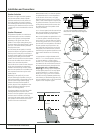
SCART A/V Connections
For the connections described above your video
device needs RCA (cinch) connectors or/and S-
Video connectors for all Audio and Video signals:
Any normal video device (Not SVHS or High 8)
for only playback needs 3 RCA jacks, VCRs for
record and playback even 6 RCA jacks. Any
S-Video device (SVHS, High 8) needs 2 RCA
(Audio) and 1 S-Video jack (Video), if it´s a play-
back unit, or 4 RCA (Audio In/Out) and
2 S-Video (Video In/Out) jacks, if it´s a recording
VCR.
Many european video devices are equipped with
RCA (Cinch) or S-Video jacks only partially, not
for all audio and video in/outputs needed as
described above, but with a so called Scart or
Euro-AV connector (almost rectangular jack with
21 pins, see drawings on next page).
In that case the following Scart to Cinch
adapters or cables are needed:
• Units for playback, such as satellite receivers,
camcorders, DVD or LD players, need an
adapter from Scart to 3 RCA plugs, see fig. 1
(normal video devices) or from Scart to 2
RCA+1 S-Video plugs, see fig. 4 (S-Video
devices).
• HiFi VCRs need an adapter from Scart to 6
RCA plugs, see fig. 2 (normal video), or from
Scart to 4 Audio+2S-Video jacks, see fig. 5
(S-Video VCR). Read carefully the instruction
attached to the adapter to find which of the
six plugs is used for the record signal to the
VCR (connect with the AVR´s Out jacks) and
for the playback signal from the VCR (connect
with the AVR´s In jacks). Do not misconnect
Audio and Video signals. Don´t hesitate to con-
sult your dealer, if you are uncertain.
• If you use only normal video devices the TV
monitor needs an adapter from 3 RCA plugs
to Scart (fig. 3) only. If also S-Video devices are
used an adapter from 2 RCA+1S-Video plugs
to Scart is needed additionally (fig. 6), con-
nected to the SCART input on your TV that is
provided for S-Video.