


PowerH SERIES
38 Owner’s Manual
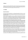
3 LOCK-LED
The LOCK-LED lights green as soon as the AES/EBU input has been synchronized to the
incoming signal and thus proper audio transmission has been established. The LOCK-LED is
dimmed with no digital audio signal being present at the input or the internal PLL not having
locked on to the incoming signal. The audio signal gets muted when the digital input has been selected.
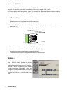
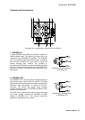
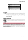
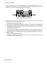
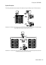
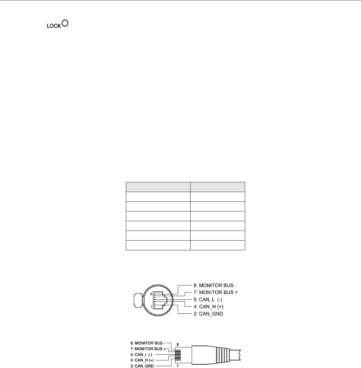
4 REMOTE CAN BUS Connection
The RCM-26 module provides two Neutrik EtherCon® RJ-45 sockets for connecting to the REMOTE CAN
BUS. These sockets are connected in parallel and serve as inputs as well as for daisy-chaining the devices
on the remote network. Cabling in a rack system can be established using commercially available RJ-45
network cables. However, CAN guidelines have to be observed for longer cable lengths. Both ends of the
CAN-bus must be terminated using 120 Ω terminating plugs. For comprehensive information and
instructions on cabling and bus length, please refer to the “CAN Bus principles“ paragraph, starting on
page 41. Along with the CAN bus, network cabling also carries a balanced audio monitoring signal. This
monitor bus allows software-controlled monitoring of input or output signals of all power amps in the
remote network, without the need for additional wiring. Nominal output level is +6 dBu (1.55 V) and
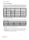
maximum output level is +21 dBu (8.7 V). The CAN bus allows using different data rates, whereas the data
rate is inversely proportional to the bus length. For smaller network setups, data rates can be as high as
500 kbit/s. For broader networks, reducing the data rate becomes necessary (down to the minimum data
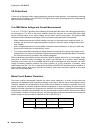
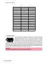
rate of 10 kbit/s). The following table illustrates the relation between data rate and bus length or network
size. The use of CAN repeaters is strongly recommended for busses that exceed 1000 meters in length.
Transfer rate (in kbit/s) Bus length (in m)
500 100
250 250
125 500
62,5 1000
20 2500
10 5000
Table 4.1: Transfer rate and bus length
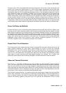
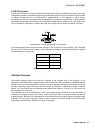
Illustration 4.6: Pin-assignment of CAN jack
Illustration 4.7: Pin-assignment of CAN plug