PowerH SERIES
10 Owner’s Manual
During installation, always separate the power amplifier from the mains. Connect the power amplifier only
to a mains network, which corresponds to the requirements indicated on the type plate.
Mains Operation & Resulting Temperature
The following tables allow the determination of power supply and cabling requirements. The power drawn
from the mains network is converted into output power to feed the connected loudspeaker systems and
into heat. The difference between power consumption and dispensed power is called power dissipation
(P
d
). The amount of heat resulting from power dissipation might remain inside of a rack-shelf and needs to
be diverted using appropriate measures. The following table is meant as auxiliary means for calculating
temperatures inside of a rack-shelf system/cabinet and the ventilation efforts necessary.
The column P
d
lists the leakage power in relation to different operational states. The column BTU/hr lists
the dispensed heat amount per hour.
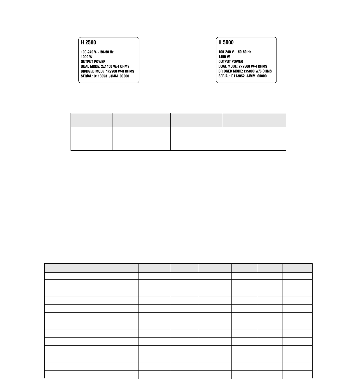
Illustration 2.3: H2500/H5000 type plate
Device Voltage Frequency Power Consumption
H2500 100-240 V 50-60 Hz 1000 W
H5000 100-240 V 50-60 Hz 1450 W
Table 2.4: Specifications for the Power Supply Unit
H2500
U
mains
in V I
mains
in A P
mains
in W P
out
in W
P
d
in W
1
BTU/hr
2
Idle 230 0.7 70 - 70 239
Max. Output Power @ 8 Ω
3
230 15.3 2420 2 x 850 720 2457
Max. Output Power @ 4 Ω
3
230 25.7 4300 2 x 1450 1400 4777
1/3 Max. Output Power @ 4 Ω
3
230 14.7 2325 2 x 483 1358 4635
1/8 Max. Output Power @ 4 Ω
3
230 6.2 875 2 x 181 513 1749
1/8 Max. Output Power @ 4 Ω
4
230 6.7 1000 2 x 181 588 2005
1/8 Max. Output Power @ 4 Ω
4
5
253 7.1 1105 2 x 219 666 2274
Normal Mode (-10 dB) @ 4 Ω
3
230 5.6 775 2 x 145 485 1655
Rated Output Power (0 dB) @ 4 Ω
3
230 23.5 3900 2 x 1200 1500 5118
Alert (Alarm) Mode (-3 dB) @ 4 Ω
3
230 16.7 2665 2 x 600 1465 4999
Max. Output Power @ 2 Ω
3
230 39.6 6920 2 x 2000 2920 9963
1/8 Max. Output Power @ 2 Ω
3
230 9.1 1345 2 x 238 870 2969
1/8 Max. Output Power @ 2 Ω
4
230 9.1 1335 2 x 238 860 2934
