


PowerH SERIES
32 Owner’s Manual
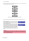
3.6 Protections
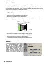
In case one of the power amp’s internal protections responds during operation, a corresponding message
appears on the LC display (or the PROTECT-LED lights) and an entry containing date, time, and protection
type is created in the event log.
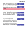
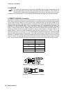
True RMS Mains Voltage and Current Measurement
PowerH SERIES amplifiers are consistently informed about the state of the mains network that they
are connected to. The CPU of the power amplifier continually computes the current RMS (Root Mean
Square, effective value) of the mains voltage and the mains current consumption. This genuine RMS
measurement has substantial advantages over the commonly used peak value measurement:
• Mains voltage measurement functions reliably even with non-sinusoidal mains networks, which, for
example, can be found with a generator-powered amplifier or when the mains voltage situation beco-
mes unstable.
• Mains voltage measurement is insusceptible to transient mains interference, as can occur when swit-
ching inductive loads such as large electric motors.
• True mains current RMS measurement allows the precise matching of the power consumption to the
characteristics of a mains circuit breaker. Detailed information about the adjustable Mains Circuit Brea-
ker Protection function is provided in the following paragraph.
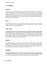
RMS measurement permanently protects the power amplifier against mains over or undervoltage. At the
occurrence of extreme mains overvoltage, the power amp switches off to prevent severe damage.
Switching on the power amp is not possible whenever mains overvoltage has been detected. The mains
voltage monitoring protection switches the power amplifier off at the occurrence of extreme mains
undervoltage (less than 70 V AC). In both cases, the blinking POWER-LED indicates the fault condition. In
case of power outage, both output channels are instantly muted then the power amplifier is shut down
within only a few milliseconds.
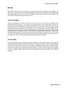
Mains Circuit Breaker Protection
The power amplifier automatically reduces the output power whenever it is driven at high levels with
extremely low-impedance loads connected resulting in the chance that the mains circuit breaker reacts.
Therefore, adjusting the characteristics of the utilized circuit breaker in Amperes is possible via the LC
display. Especially at extremely high/low ambient temperatures or when connecting the power amplifier
together with other equipment to a single common automatic circuit breaker, it might become necessary to
manually set an Ampere value that differs from the circuit breaker’s nominal value to ensure that the Mains
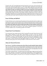
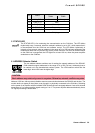
Circuit Breaker Protection functions optimally. The following table outlines the allowable value ranges and
default settings for the two modes of operation at 120 V and 220-240 V.
Operation Minimum Maximum Factory Settings
120 V 6 A 40 A 30 A
220-240 V 6 A 30 A 16 A
Table 3.4: Mains Circuit Breaker Protection