


PowerH SERIES
Owner’s Manual 17
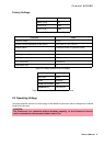
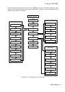
Output (Speakon-type Connectors / Terminals) in Normal Mode
With PowerH SERIES amplifiers speaker connection differs depending on the actually selected
mode of operation of the power amplifier blocks, i.e. the setting of the MODE switch on the power amp’s
rear panel. In NORMAL mode, the loudspeaker systems can be connected in two different ways: using
typical Speaker Systems Cabling or Bi-Amp Cabling.
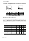
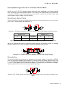
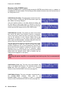
Typical Speaker System Cabling
The first possibility is to use the two Speakon-type connectors, whereas speakers have to be connected to
pins 1+ and 1– of the sockets, see illustration 2.13.
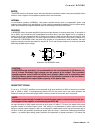
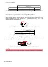
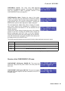
Next to the Speakon-type sockets, conventional speaker terminals are provided as well. The following
illustration shows how to connect the speaker systems for NORMAL mode operation.
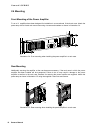
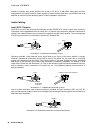
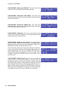
Bi-Amp Cabling
The second possibility for connecting the speakers when the power amplifier is operated in NORMAL
mode is to only use the Speakon-type connector CH A and to connect one speaker cabinet to pins 1+ and
1–, as described above and the second cabinet to pins 2+ and 2– as shown in illustration 2.15. Only pins
2+ and 2– of the Speakon CH A connector are assigned. Proceeding like this facilitates the cabling of
speaker systems that are used in active 2-way operation (Bi-Amp).
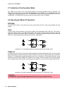
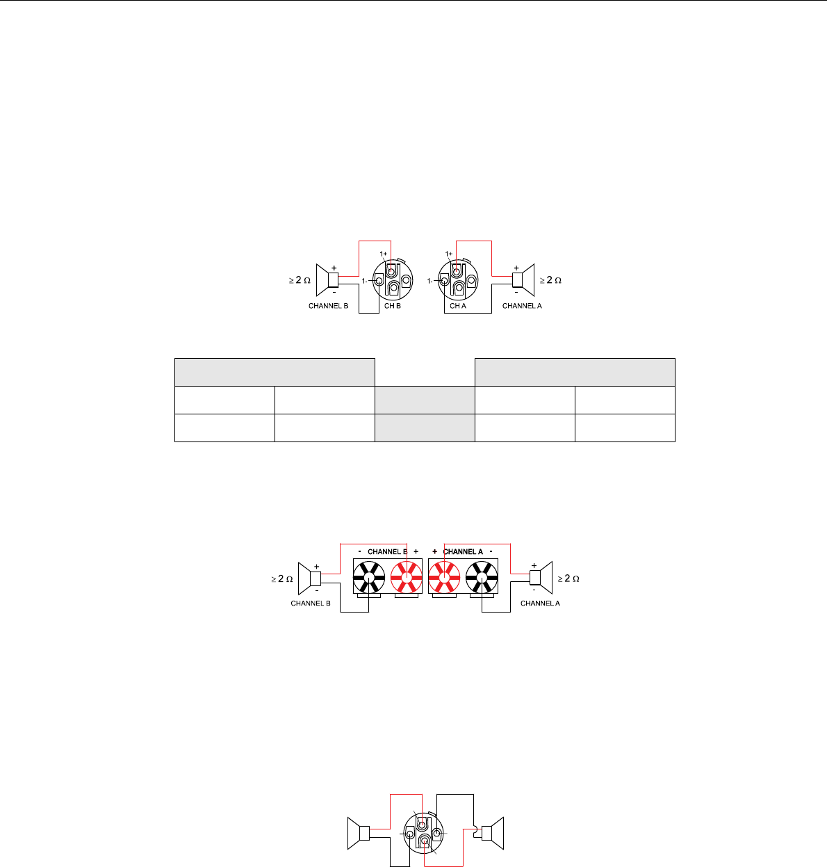
Illustration 2.13: Speaker connection in NORMAL operation mode, using Speakon A and B connectors
Speakon CH B Speakon CH A
1+ 1-
Connector 1+ 1-
B+ B-
Assignment A+ A-
Table 2.5: Speaker connection in NORMAL operation mode, using Speakon A and B connectors
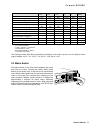
Illustration 2.14: Speaker connection in NORMAL operation mode, using Terminals
Illustration 2.15: Bi-Amp speaker connection in NORMAL operation mode, using only the Speakon A con-
nector
1+
2+
1-
2-
CH ACHANNEL A CHANNEL B
+
-
+
-
≥ 2 Ω≥ 2 Ω