


PowerH SERIES
16 Owner’s Manual
installer to consider each power amplifier with a gain of 35 dB (or 32 dB) when setting gain structure,
independent of the actual maximum output capacity of each individual power amp. Any limiters have to be
adjusted to maximum power handling capacity of the loudspeaker components.
Audio Cabling
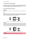
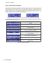
Input (XLR / Phoenix)
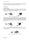
Inputs IN A and IN B are electronically balanced and the SENSITIVITY switch controls input sensitivity.
Connection can be established either by using XLR- or Phoenix-type connectors, which are connected in
parallel. The needed Phoenix-type connectors are supplied with the power amplifier. The pin-assignment
of XLRF-type connectors is in accordance with the IEC standard 268.
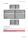
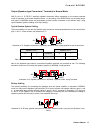
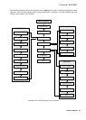
Whenever possible, using balanced audio signal feeds at the input of the power amplifier is always
preferred. Unbalanced connections should only be used if the cables are very short and no interfering
signals are to be expected in the vicinity of the power amplifier. In this case, bridging the screen (shielding)
and the pin of the inverting input inside of the connector is mandatory. Otherwise, a 6 dB drop in level
could result. Please also see illustration 2.11. Due to their immunity against external interference sources,
such as dimmers, mains connections, HF-control lines, etc., using balanced cabling and connections is
always preferable.
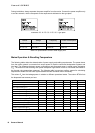
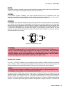
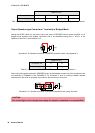
Next to its input connector, each channel provides an individual XLR-type connector (OUT A or OUT B),
which is connected in parallel to allow for comfortably daisy-chaining the audio signal for the connection of
additional audio equipment.
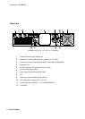
Illustration 2.10: Balanced connection of input
Illustration 2.11: Unbalanced connection of input
Illustration 2.12: Balanced connection of output (Daisy-Chain)
1, SHIELD
3, COLD
2, HOT
COLD, -
HOT, +
SHIELD
3, COLD
2, HOT
JUMPER
FROM COLD
TO SHIELD
JUMPER FROM COLD TO SHIELD
HOT, +
SHIELD
1, SHIELD
2, HOT
3, COLD