


Step 3
Step 4
Step 5
Step 6
Step 7
48
Installation Procedures
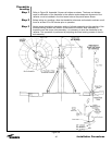
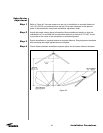
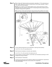
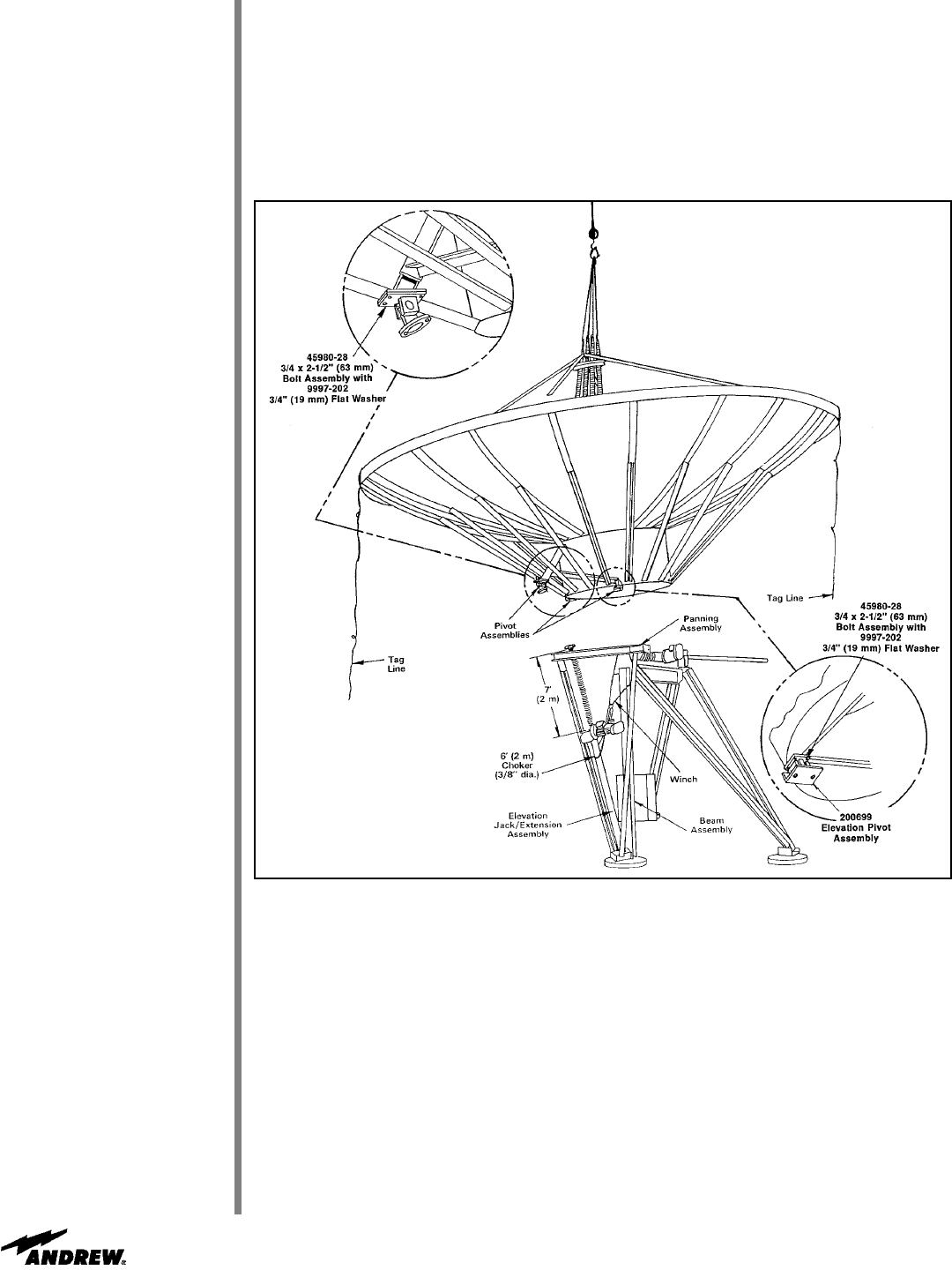
Refer to Figure 46. Extend elevation jack extension assembly to 7 ft (2 m) dimension as
shown. Raise assembly and secure to forward ground mount beam assembly, using 6 ft
(2 m) choker and winch assembly.
Warning: Do not attempt to raise reflector/backstructure if winds exceed 25 mph. Raise
reflector/backstructure assembly and align with corresponding elevation jack/panning frame
assemblies using tag lines for guidance.
Note: A minimum of three tag lines should be used during high wind conditions. Do not exert
force while using the tag lines during reflector installation as this will distort the panel surfaces.
Figure 46
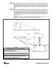
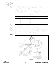
Connect reflector/backstructure pivot assemblies to panning frame assembly.
• Use 7/8 x 2-1/4 in (57 mm) bolts and nuts
Attach tripod pivot assembly to elevation jack assembly.
•
Use 7/8 x 2-1/2 in (63 mm) bolts, flat washers and nuts
Securely tighten mounting hardware on both sides of pivot assembly according to A-325
Hardware Tensioning Procedure.
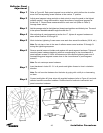
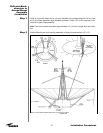
Install subreflector subassembly.
• Use 3/4 in (19 mm) jam nuts and washers making sure the subreflector is repositioned
in the exact location determined at the conclusion of its adjustment.
Secure all hardware.