


Step 3
Step 4
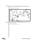
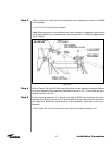
Step 5
23
Installation Procedures
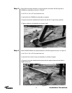
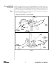
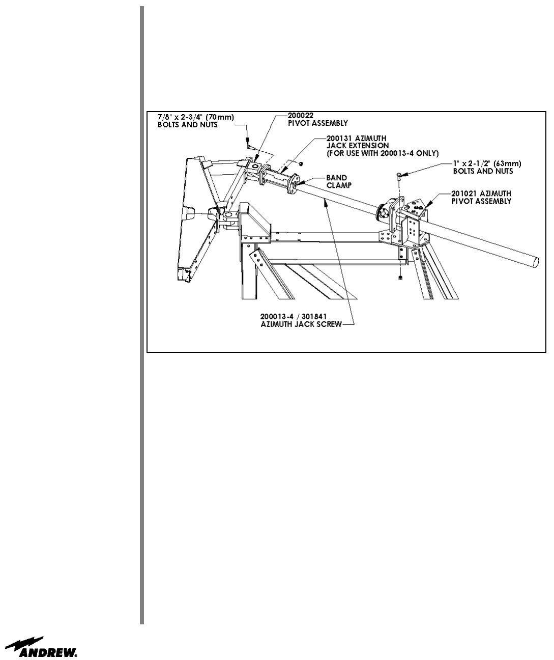
Figure 18
Refer to Figure 18. Raise the azimuth pivot/jack screw assembly, and attach to 200088A
joint assembly.
•
Use 1 by 2-1/2 inch (63 mm) hardware.
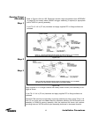
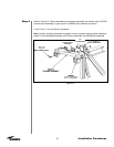
Note: Mounting position of azimuth/pivot jack screw assembly is dependent upon azimuth
range requirements and corresponds with mounting position of 200035 outrigger assem-
bly (if utilized).
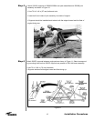
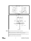
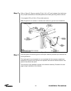
Refer to Figures 19A and 19B. After azimuth pivot/jack screw assembly has been attached
to the joint assembly, attach remaining hardware as shown to 1/2” (13 mm) stud and apply
supplied Loctite to all nuts.
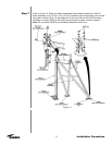
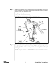
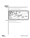
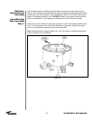
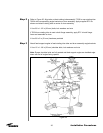
Position panning assembly to 0° azimuth and align 200022 pivot assembly with corre-
sponding azimuth jack screw or 200131 azimuth jack extension. Remove band clamp from
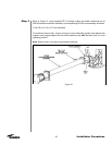
jack screw boot. Rotate jack screw to extend to pivot assembly. Attach jack screw to pivot
assembly.
• Use 7/8 by 2-3/4 in (70 mm) bolts and nuts (P/O jack assembly hardware kit.)