


34
Installation Procedures
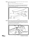
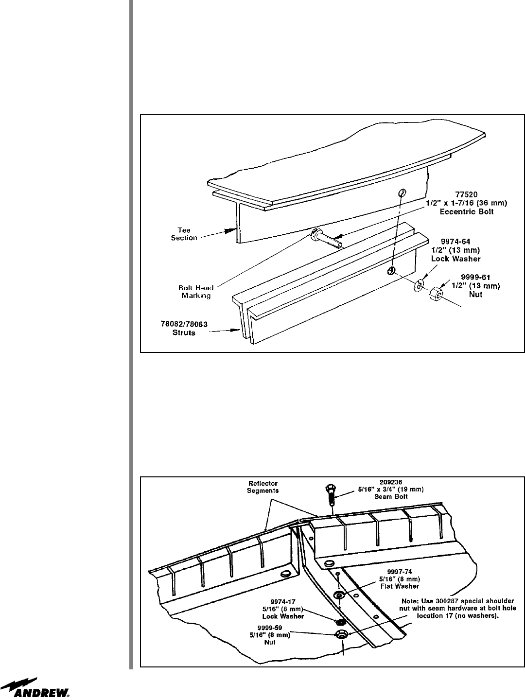
Step 4
Step 5
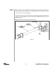
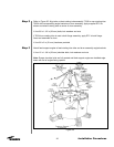
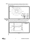
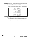
Refer to Figure 30. Install reflector segment formed tee section between corresponding
back strut members and attach.
• Use 1/2 x 1-7/16 in (37 mm) eccentric bolt, lock washer and nut
Note: Ensure eccentric bolt is fully seated and bolt head marking is positioned at right
angle to panel segment. It is recommended stick wax be applied to the shaft of the
eccentric bolt to facilitate its insertion and later adjustment. All 20 eccentric bolt head
markings must be at right angles to panel.
Figure 30
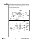
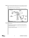
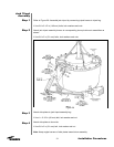
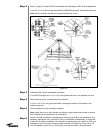
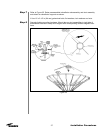
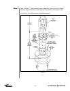
Refer to Figure 31. Install remaining reflector panels opposite each other to balance the
enclosure assembly being sure to install panel segment seam hardware finger tight in
holes 1-28. Note that screw locations in reflector segments are numbered 1-31 from the
center out. Panel segment seams are numbered 1-20. Use special nut with shoulder at
hardware location 17 on all 20 panel segment seams. Tighten until nut shoulder is prop-
erly seated inside the formed Tee section hole.
Note: Do not place hardware in holes 29-31 at this time.
Figure 31