


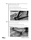
Step 3
Step 4
15
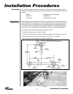
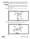
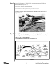
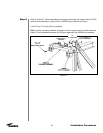
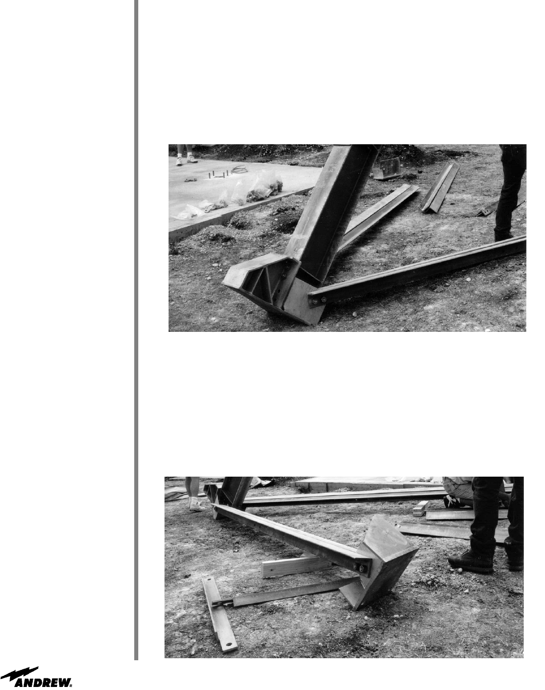
Raise 200114A beam assembly to upright position and attach 200109 supports to
200068 joint assembly as shown in Figure 8.
• Use 7/8 x 2-1/4 in (57 mm) bolts and nuts
•
Insert bolts from 200068 joint assembly to supports
• Supports should be installed back-to-back with the flat of angle facing upwards
• Tighten supports until assembly can support itself
Installation Procedures
Figure 8
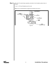
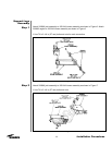
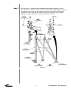
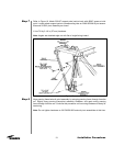
Attach 200063/200064 rear pad assemblies to 200109 supports as shown in Figure 9.
• Use 7/8 x 2-1/4 in (57 mm) bolts and nuts
• Insert bolt from inside of rear pad assembly to outside of support
• Supports should be installed back-to-back with the edges forward and the flats of
angles facing rear
Figure 9