


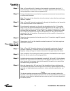
Subreflector
Offset Tilt
Adjustment
Step 1
Step 2
Step 3
Step 4
Step 5
46
Installation Procedures
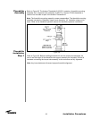
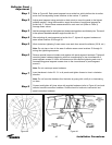
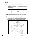
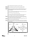
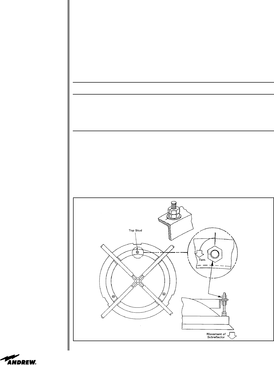
Refer to Table 4 and Figure 43. Adjust top subreflector jam nuts (two) the distance indi-
cated according to the offset pointing angle in Table 4. Make the desired adjustment
using the floating ring and subreflector jam nuts.
Note: Before making any adjustment, mark the starting position of the jam nuts in rela-
tion to the floating ring with a pencil, then mark the floating ring to indicate the proper
distance of the turn.
Table 4
Offset Operating Angle Top Stud Nut Adjustment
10° - 20° 1-3/4 turns
30° 1-5/8 turns
40° 1-1/2 turns
50° 1 turn
60° 7/8 turn
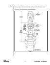
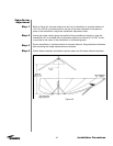
Table 4 shows the distance the subreflector must be lowered. Use only the top adjust-
ment stud to obtain the proper offset tilt.
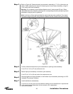
Once the offset tilt adjustment is completed, do not disturb adjustments.
Match mark the subreflector subassembly and the floating ring. Remove 3/4” (19 mm) jam
nuts and washers and lower the subreflector subassembly. Place subreflector subassem-
bly in safe location to secure it from damage during reflector/backstructure installation.
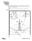
Remove theodolite and theodolite mounting assembly from feed support tube.
Figure 43