


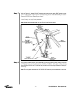
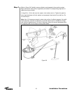

Reflector/
Backstructure
Assembly
Feed Rotating
Tube Assembly
Step 1
29
Installation Procedures
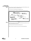
Type A-325 hardware is utilized during the reflector attachment to the ground mount.
Use of A-325 hardware eliminates slippage between mating surfaces under high loading
conditions as well as the need for future retightening. Refer to the A-325 tensioning pro-
cedure in preceding installation text. CAUTION: Adhere to any special instructions sten-
ciled on crate relative to crate opening, contents removal and/or personnel safety.
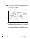
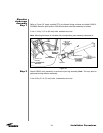
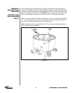
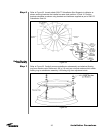
Refer to Figure 24. Position six temporary supports in center of assembly area 60” apart
in a 7 ft (2 m) diameter circle. Place drum assembly on temporary supports as shown
with drum tab positioned opposite ground mount assembly.
Note: Supports should be approximately 18 in (457 mm) high and placed between bolt
holes on bottom of drum assembly.
Figure 24