


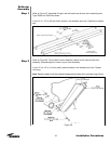
Step 2
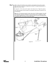
Step 3
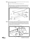
Step 4
Step 5
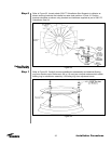
Step 6
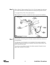
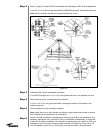
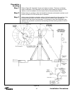
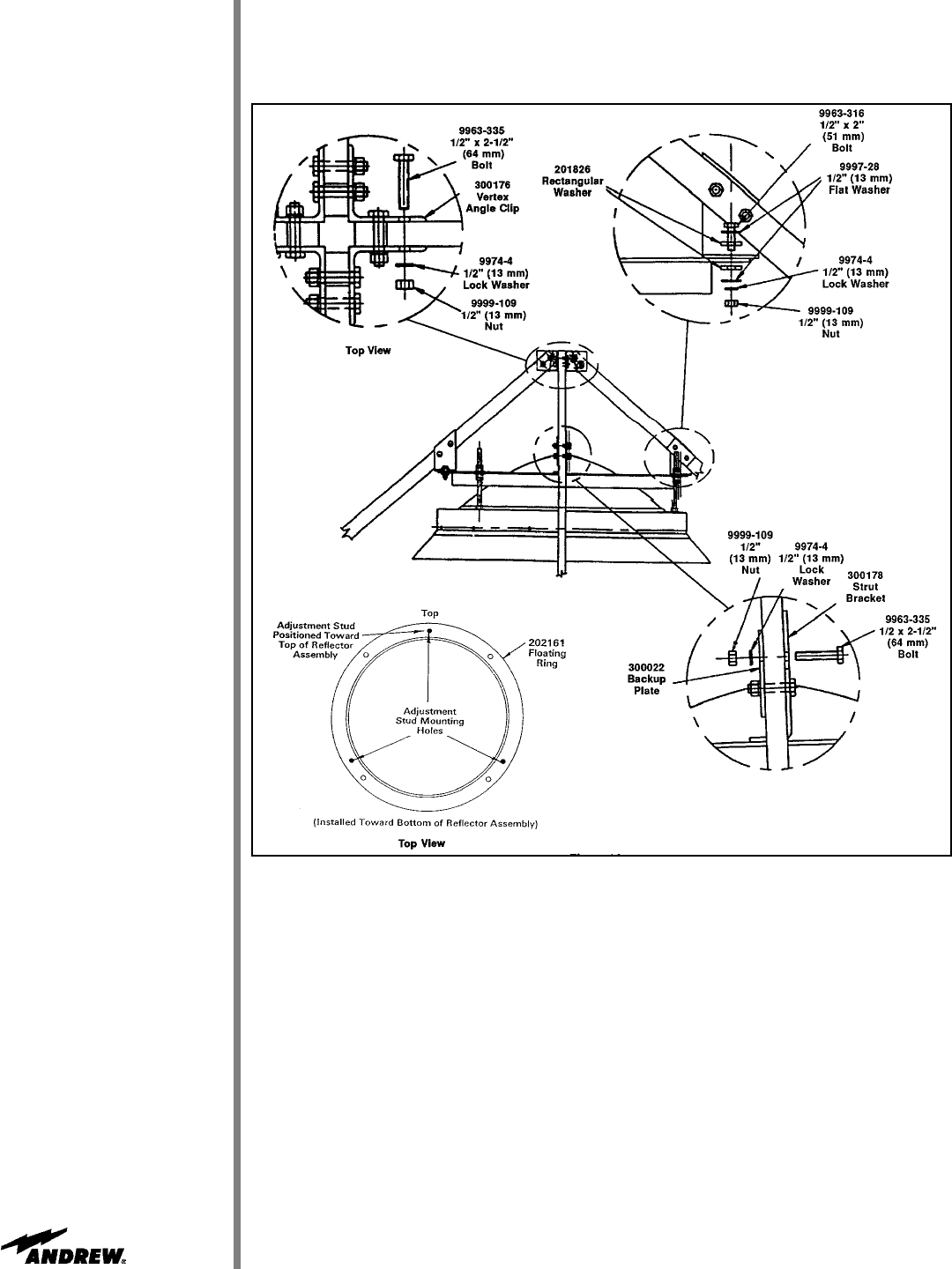
Refer to Figure 34. Attach 300178 Subreflector Strut Brackets to 300174 Strut Assemblies.
• Use 1/2 x 2-1/2 in (64 mm) galvanized bolts, 300022 backup plates, lock washers and nuts.
Note: All strut brackets should face counterclockwise as shown.
Figure 34
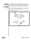
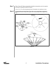
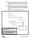
Assemble 300174 strut assemblies as shown.
• Use 300176 angles and 1/2 x 2 in (51 mm) galvanized bolts, lock washers and nuts.
Attach floating ring to corresponding strut brackets.
• Use 1/2 x 2 in (51 mm) galvanized bolts, rectangular washers, flat washers, lock
washers and nuts.
Securely tighten all strut assembly hardware.
Note: Apply stick wax to strut bracket and floating ring surface contact areas to ensure
free movement during adjustment of subreflector.
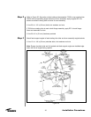
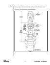
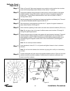
Attach 202123B subreflector subassembly to floating ring. Ensure top subreflector sub-
assembly adjustment stud, opposite of notch in subreflector subassembly, is positioned
toward top of reflector assembly. Lift subreflector subassembly and insert 8 in (203 mm)
subreflector studs into three mounting holes provided in floating ring. Install 3/4 in (19
mm) flat washer and two 3/4 in (19 mm) jam nuts stud as shown. Snug hardware.