


17
Installation Procedures
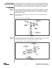
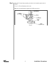
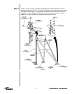
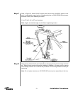
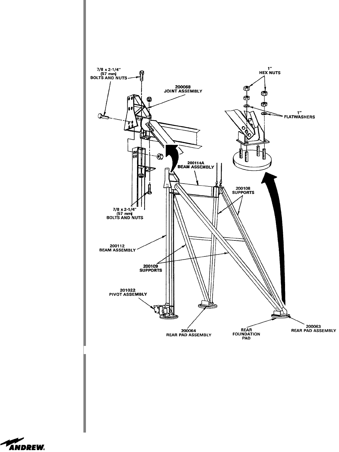
Step 7
Refer to Figure 12. Raise and attach assembled beam/support assembly to 200112
beam assembly using 7/8 by 2-1/4 in (57 mm) hardware and corresponding rear founda-
tion pads as shown using 1 in flat washers and hex nuts. Ensure all A-325 mounting
hardware is in place. Begin A-325 tensioning procedure at pads, and work upward.
Note: Do not tighten 201022 pivot assembly hardware at this time.
Figure 12