


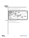
Step 7
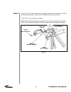
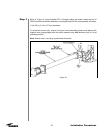
Step 8
21
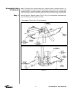
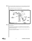
Installation Procedures
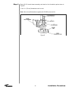
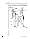
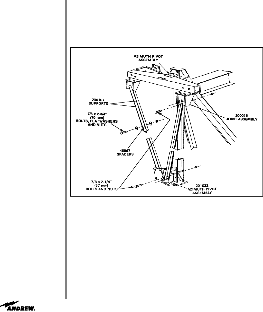
Figure 16
301786
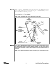
Refer to Figure 16. Attach 200107 support pairs back-to-back with 45967 spacer at mid-
point. Loosely attach support pairs to corresponding tabs on 200015/200016 joint assem-
blies and 201022 pivot assembly as shown.
• Use 7/8 by 2-1/4 in (57 mm) hardware
Note: Angles are attached edge out with flat of angle facing inward.
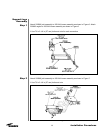
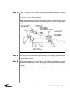
Align panning frame/azimuth pivot assembly by swinging panning frame through its entire
arc. Slightly snug panning frame/pivot assembly hardware, and again swing panning
frame through its entire arc. Continue this procedure until mounting hardware is ready for
tensioning.
Note: Do not tighten hardware on 301786/201022 azimuth pivot assemblies at this time.