


Step 4
Step 5
41
Installation Procedures
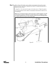
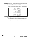
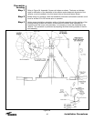
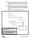
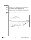
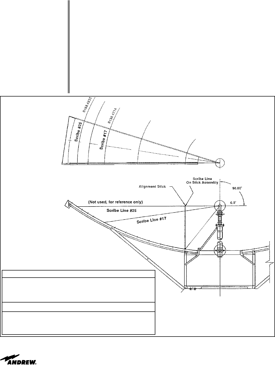
Refer to Figures 38 and 39. With the height of the theodolite and its support kit set as
indicated in Figure 24, the theodolite should sight near the scribe line of the alignment
stick when theodolite elevation is set to 90° 00’ 00”. If not, set the theodolite elevation
angle to 90° and move the theodolite up or down until it sights on the scribe line using
the rotary precision lift. Be careful not to turn entire torque tube while turning precision
lift.
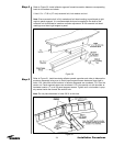
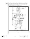
Focus and adjust theodolite elevation to the scribe line and record this reading as Rl.
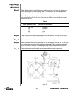
Relocate stick, rotate theodolite, focus and adjust theodolite elevation to scribe line and
record this reading as R2. Add Rl and R2 readings and divide by 2. Record this reading
as R3. Adjust theodolite elevation angle to new angle R3. Rotate the tribach assembly
adjustment screw (in line with the alignment stick) up or down until the theodolite is
sighted on the scribe line. Repeat this procedure for the diagonally opposed alignment
stick positions.
Note: Only 2 of the 3 tribach adjustment screws should be used for leveling. Mark or
identify 1 of the 3 and only use the remaining 2 adjustment screws.
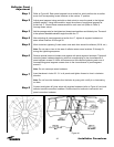
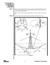
Figure 39
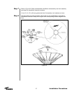
Brief Description of Theodolite Calibration Sequences:
1. Theodolite Leveling (Sect. 10.0)
2. Theodolite Centering (Sect. 11.0)
3. Theodolite Height Adjustment (Sect. 12.0)
4. Repeat 1 - 3 as Necessary (Typically 4 - 5 times) to Achieve Calibration Specs.
Theodolite Calibration Specifications:
1. Leveling: All 3 Stick Positions Within 15 Seconds of Each Other.
2. Centering: All 3 Center Reading to be Within 15 Seconds of Each Other.
3. Height: All 3 Level Position Readings Within 10 Seconds of 90° 00’ 00”.
4. Ready for Reflector Panel Adjustment (Sect. 13.0).
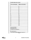
Table 2