


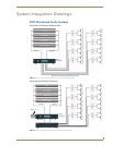
System Integration Drawings
22
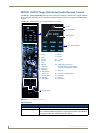
Tango Series Audio Controllers
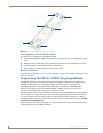
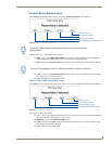
RF Interference
Shielded cable is generally not required for audio installations. Although the Tango Controller does generate
radio emissions, it uses a digital signaling path during command entry.
These emissions have been accommodated for in design and conform to RF emission standards. There are
normally no ongoing data communications in the circuit path. Communications only occur at the time a
command is issued from a zone. However many other systems do use microprocessor systems where the
cabling may be in close proximity such as telephone and security systems, and it is possible for different
systems to interfere with each other.
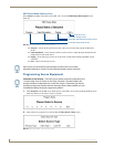
If you face an installation where your cable runs are in parallel to these types of systems you may consider
shielded cable to the keypads. In this case ground the drain wire by connecting it to the chassis of the Tango
Controller.
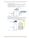
Distribution Wiring
In general, wiring is installed in a single continuous run between the Tango Controller, the Keypad and the
speaker location. Other cable routing options such as a home run to a common wiring distribution point,
integration with home automation systems, or split zone applications can be significantly different than the
general information presented here. These applications are left to the installer’s discretion and experience.
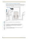
Examples of common wiring options can be found in the Special Wiring Configurations section of this
document.
SWT - Special Wiring Configurations
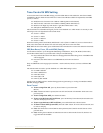
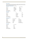
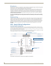
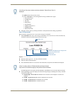
Auxiliary Amplifier Configuration
In some cases you may require more power for a given zone than the Tango Controller, or Carbon XA can
provide. You may purchase a DAS-LLC to provide a line level output to incorporate a larger external amplifier,
or you can make your own line level converter.
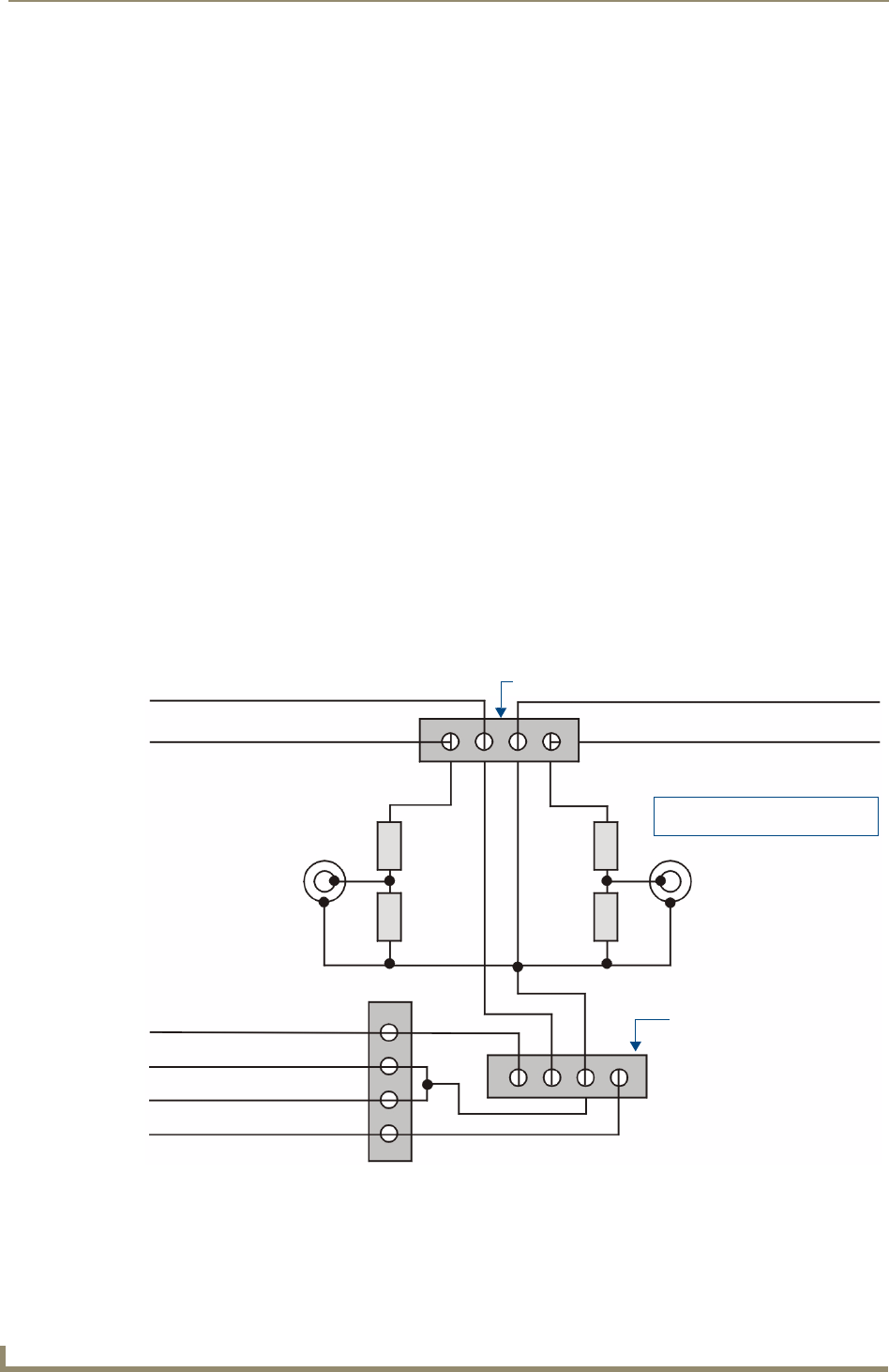
FIG. 17 shows the construction of a simple circuit of discrete components to reduce the "speaker level" output
of the Tango Controller to “line level" so that it can drive an auxiliary amplifier.
This amplifier would typically be installed at the equipment rack (head end).
FIG. 17 Auxiliary Amplifier Configuration
Tango Controller
Zone Output Terminal Connector
DATA
Ground (-)
Left Speaker
Right Speaker
Left RCA Jack to Amp Right RCA Jack to AMP
R1
R2
R3
R4
Left Speaker (+)
Right Speaker (+)
Left Speaker (-)
Right Speaker (+)
KP Series Keypad
R1, R3 = 47K 1/4 Watt Resistor
R2, R4 = 10K 1/4 Watt Resistor
Terminator