34 C
HAPTER
3: I
NSTALLING
AND
O
PERATING
THE
VCN A
CCESS
P
OINT
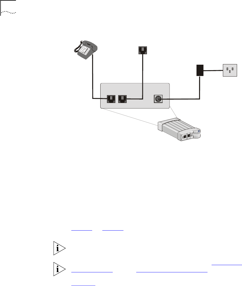
Figure 25
Preparation of the
VCN Access Point
■
Connect an RJ-45 cable from the user’s PC to the Ethernet port at the
front of the VCN AP. The user’s PC must be equipped with an Ethernet
card. If the user’s PC does not have an Ethernet card installed, the
modem card connects in the Fax-Modem port at the front of the VCN
AP. In such case, the data does not go through the VDSL line and
cannot make use of the 10 Mbps full duplex connectivity.
■
If the telephone set has an additional RJ-11 port, it can be used
independently of the VCN AP for fax or modem.
Thirty seconds after the VCN AP is connected to power, check that the
Power and Line LEDs on the VCN AP front panel are green. Refer to
Figure 8
on page 23.
The VCN AP does not have an ON/OFF switch. The unit is powered on as
soon as it is connected to ac power.
If the LEDs on the VCN AP do not turn green, refer to Appendix A
Troubleshooting
, section “Power-on Self Test (POST)”.
Figure 26
illustrates the VCN Access Point-VCN Access Concentrator
network after the VCN AP is installed and a user computer is attached to
the VCN AP. The user has both access to the Public Switched Telephone
Network (PSTN) and a high speed connection to an Internet Service
Provider (ISP) as well as an additional connection to a fax or Modem.
telephone
socket
ac/dc
adapter
ac power
socket
VCN Access Point
DC-IN
LINE
PHONE


