


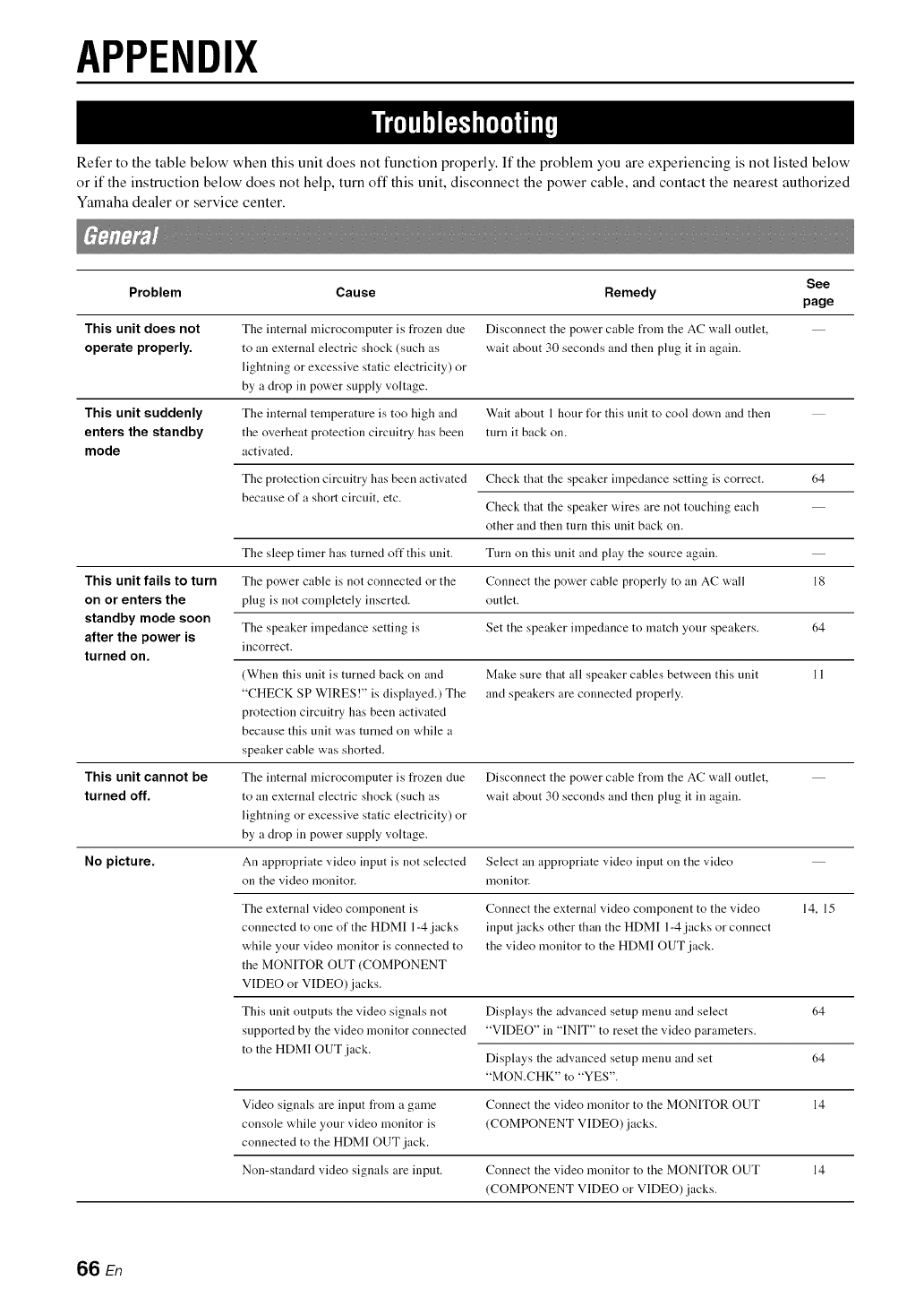
APPENDIX
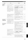
Refer to the table below when this unit does not function properly. If the problem you are experiencing is not listed below
or if the instruction below does not help, turn off this unit, disconnect the power cable, and contact the nearest authorized
Yamaha dealer or service center.
See
Problem Cause Remedy
page
This unit does not The internal nlicrocomputer is frozen dne Disconnect the power cable from the AC wall outlet,
operate properly, to an external electric shock (such as wait about 30 seconds and then plug it in again.
lightning or excessive static electricity) or
by a drop in power supply voltage.
The internal temperature is too high and
the overheat protection circuitry has been
activated.
This unit suddenly
enters the standby
mode
This unit cannot be
turned off.
Wait about 1 hour fur this unit to cool down and then
turn it back on.
The protection circuitry has been activated
because of a short circuit, etc.
Check that the speaker impedance setting is correct. 64
Check that the speaker wires are not touching each
other and then turn this unit back on.
The sleep timer has turned off this unit. Tnrn on this unit and play the source again.
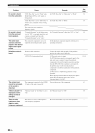
This unit fails to turn The power cable is not connected or the Connect the power cable properly to an AC wall 18
on or enters the plug is not completely inserted, outlet.
standby mode soon
The speaker impedance setting is Set the speaker impedance to match your speakers. 64
after the power is
incorrect.
turned on.
(When this unit is turned back on and Make sure that all speaker cables bet'a, een this unit 11
"CHECK SP WIRES !" is displayed.) The and speakers are connected properly.
protection circuitry has been activated
because this unit was turned on while a
speaker cable was shorted.
The internal microcomputer is frozen due
to an external electric shock (such as
lightning or excessive static electricity) or
by a drop in power supply voltage.
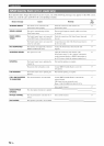
No picture. An appropriate video input is not selected Select an appropriate video input on the video
on the video monitor, monitor.
The external video component is Connect the external video component to the video 14, 15
connected to one of the HDMI 1-4 jacks input jacks other than the HDMI 1-4 jacks or connect
while your video monitor is connected to the video monitor to the HDMI OUT jack.
the MONITOR OUT (COMPONENT
VIDEO or VIDEO)jacks.
This unit outputs the video signals not
supported by the video monitor connected
to the HDMI OUT jack.
Disconnect the power cable from the AC wall outlet,
wait about 30 seconds and then plug it in again.
Displays the advanced setup menu and select
"VIDEO" in "INIT" to reset the video parameters.
Displays the advanced setup menu and set 64
"MON.CHK" to "YES".
Video signals are input from a game Connect the video monitor to the MONITOR OUT 14
console while your video monitor is (COMPONENT VIDEO)jacks.
connected to the HDMI OUT jack.
Non-standard video signals are input. Connect the video monitor to the MONITOR OUT 14
(COMPONENT VIDEO or VIDEO) jacks.
64
66 En