


2.
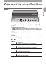
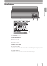
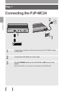
LAN port
For connecting the product to network equipment (such as a personal computer, router or
hub) with a LAN cable.
A LINK LED (left side) and a SPEED LED (right side) are above every LAN port.
• LINK LED: The LINK LED blinks if data is being sent and lights if a link has been
established. If the LINK LED is off, there is no link.
• SPEED LED: The SPEED LED does not light when 10BASE-T is used and lights when
100BASE-TX is used.
3. AUDIO IN terminal
Connect this terminal to the line output terminal on an audio device or PC.
4. AUDIO OUT terminal
Connect this terminal to the line input terminal on an audio device or PC.You can connect
a commercial IC recorder to record voice during a conference.
5. CONSOLE port
Connect the RS-232C terminal (serial connector) on a PC if you want to change the
settings of this product or when you forget your password. For more information, see
“Changing Settings from the CONSOLE Port” (page 74) or “If You Forget Your Password”
(page 85).
6. INIT switch
You can revert your PJP-MC24 to the factory settings by turning on the power while
pressing this switch.
For details, see “Initializing the PJP-MC24” (page 84).
7. Vent holes
Help to prevent overheating.
12
Introduction