


ISM4 INSTALLATION & PROGRAMMING MANUAL
7
When Source 1 (System Reference Device) is turned ON, the Sensor Module for that device will show an ON
state (+12V) to the Source 1 “Sense In”. The first task that the ISM4 will take is to launch the ON Macro for
Source 1. Based on the discussion above, the entire macro will be executed with the exception of the IR
content of Command Structure 1. The ISM4 will then ‘look’ at the ON/OFF state of Sources 2-4. If any is
sensed to be OFF, it will be turned ON utilizing its associated ON Macro. If at any time that Source 1 (System
Reference Device) is ON, any of the other Sources is sensed to be OFF, the ISM4 will output the ON Macro
associated with that device to sync it with the system. (System ON Mode)
When Source 1 (System Reference Device) is turned OFF, the Sensor Module for that device will show an
OFF state (0V) to the Source 1 “Sense In”. The first task that the ISM4 will take is to launch the OFF Macro
for Source 1. Based on the discussion above, the entire macro will be executed with the exception of the IR
content of Command Structure 1. The ISM4 will then ‘look’ at the ON/OFF state of Sources 2-4. If any is
sensed to be ON, it will be turned OFF utilizing its associated OFF Macro. If at any time that Source 1
(System Reference Device) is OFF, any of the other Sources is sensed to be ON, the ISM4 will output the
OFF Macro associated with that device to sync it with the system. (System OFF Mode)
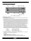
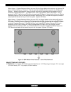
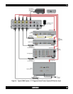
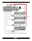
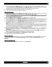
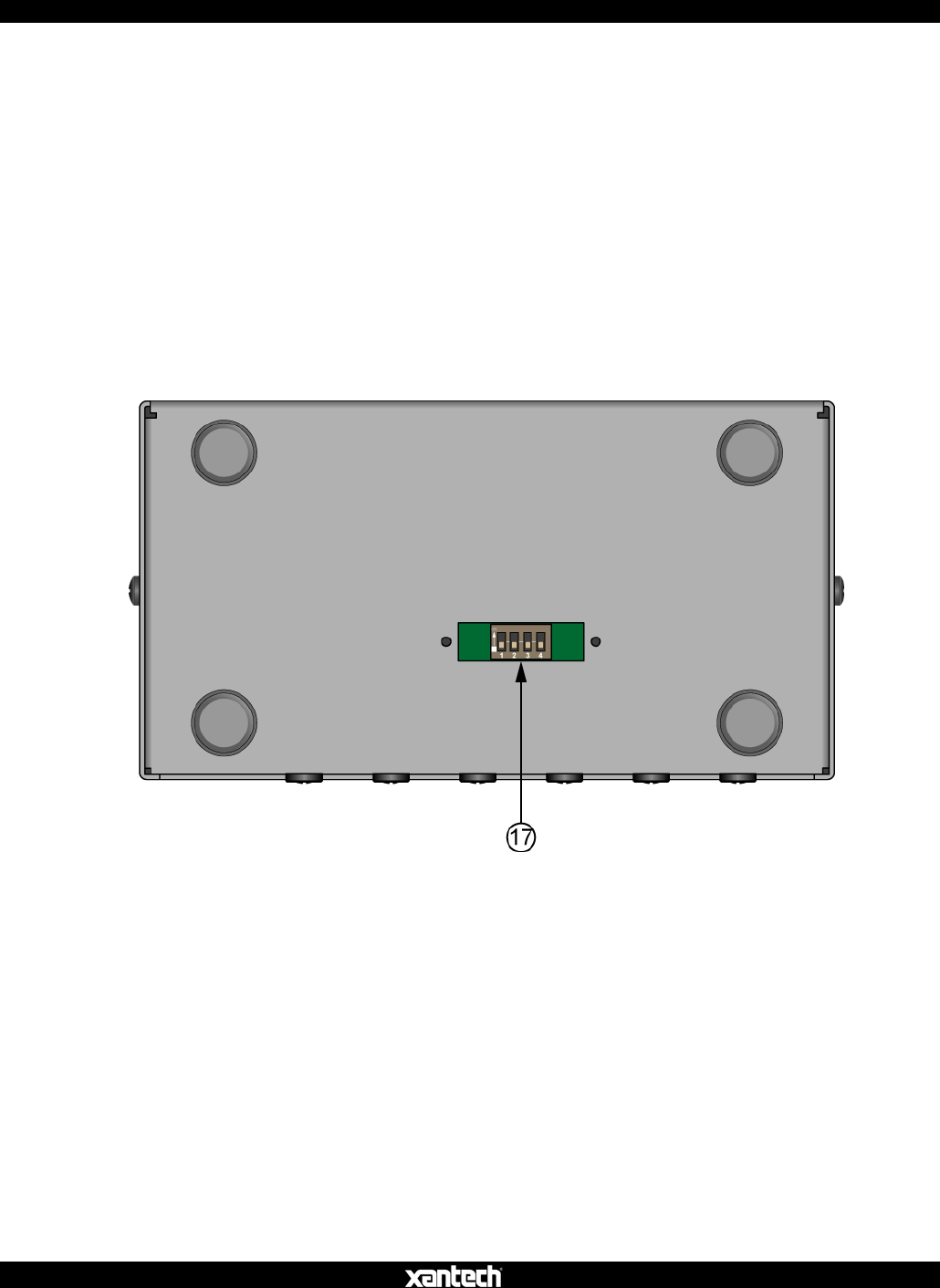
Figure 3 – ISM4 Bottom Panel Features – Cover Plate Removed
ISM4 BOTTOM PANEL FEATURES
17. DIP Switch. Four Position DIP Switch sets associated Source 1-4 IR Output signal strength. ON = low output
(470 ohm resister) OFF = high output (100 ohm resister).