ISM4 INSTALLATION & PROGRAMMING MANUAL
5
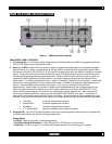
Edit Mode
• Solid Green – Program ON state Macro.
• Solid Orange – Program OFF state Macro.
• Solid Red – Program Error.
4. Prev Button. This button has multiple functions, depending upon ISM4 programming mode including:
Navigate Backwards through Source ON/OFF Macros, Navigate Backwards through Macro Command
Structures (individual commands and delays) within ON/OFF Macros, decrease individual Delay value, Exit
Programming Mode and Initiate the Clone Process to copy the Macro Tables from one ISM4 to another ISM4.
5. Test Button. This button has three functions, depending upon the ISM4 programming mode including: Test
Source Macro, Test Learned IR Command and Test Delay.
6. Next Button. This button has three functions, depending upon the ISM4 programming mode including:
Navigate Forward through Source ON/OFF Macros, Navigate Forward through Macro Command Structures
(individual commands and delays) within ON/OFF Macros and Increase individual delay value.
7. Delay Button. This button is used during Source ON/OFF Macro programming to allow setting a delay
duration within a Command Structure.
8. Sequence Button. This button has multiple functions, depending upon the ISM4 programming mode
including: Enter Source ON/OFF Macro Programming Mode, Enter IR Learn Mode, Save Learned IR and
Save Delay Value.
9. Delete Button. This button has multiple functions, depending upon ISM4 programming mode including:
Delete selected Source ON/OFF Macro, Delete Command Structure, Delete entire Macro Table (all macros),
remove last unsaved Learned IR Command, Remove Delay from selected Command Structure.
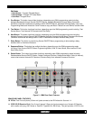
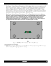
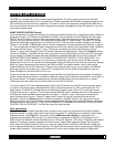
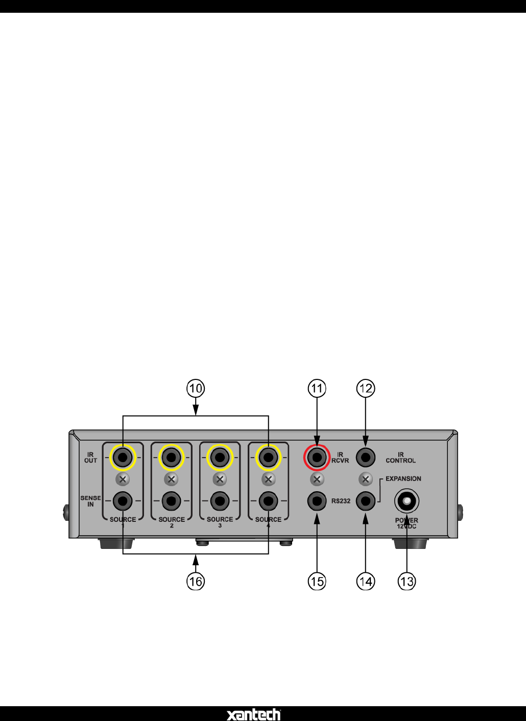
Figure 2 – ISM4 Rear Panel Features
ISM4 REAR PANEL FEATURES
10. IR Out. Four 2-circuit (mono) 3.5mm mini jacks connect to the IR Emitters for Sources 1-4.
11. IR RCVR (IR Receiver Port). One 3-circuit (stereo) 3.5mm mini jack connects to any Xantech IR Receiver
with a stereo mini plug. (291 Series or ‘Dash 30’ Type 480-30, 490-30 etc). This jack provides 12 VDC to the


