


ISM4 INSTALLATION & PROGRAMMING MANUAL
11
SYSTEM APPLICATIONS
The ISM4 is a versatile device with endless possible applications. For the purpose of this manual, two basic
applications will be described. One is a typical Home Theater application with the ISM4 managing system sync for
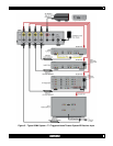
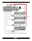
an A/V Receiver and three source components. The other is a multi-zone application integrating the ISM4 with a
multi-zone controller that does not provide intelligent source power management to keep the sources in sync with
whole-house system status.
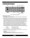
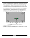
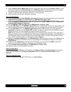
HOME THEATER SYSTEM (Figure 4)
In this configuration, all system components can either be controlled directly with a programmed system remote or
exclusively through an IR Receiver connected to the ISM4. In this configuration the A/V Receiver will be turned
ON/OFF with the remote (or receiver front panel power button). When the receiver turns ON, the switched AC
Outlet on the rear panel will also turn ON, energizing the connected 12V Power Supply. The SMVLT01 Voltage
Sensor will detect the change of state, (in this case from OFF to ON) and show a control voltage to the Source 1
“Sense In” on the ISM4. (ISM4 System Status is always referenced to the device sensed by the Source 1 “Sense
In”). The first task that the ISM4 will take in response to the Off-to-On transition is to execute the Power ON Macro
associated with the Source 1 “Sense In” input. Recall that in executing this macro (launched by a Source 1
“Sense In” trigger) the IR content of the first Command Structure will be bypassed. Refer to the Sense In section
for further information. The ISM4 will then ‘look’ at the other Source Sense Inputs and if they are OFF (no sensor
control voltage), the ISM4 will output the Power ON Macros associated with each source to turn them ON. THE
SYSTEM POWER ON COMMAND IN THE REMOTE SHOULD ONLY CONTROL THE A/V RECEIVER. The
ISM4 will control the other devices for turn ON and sync. Additionally, each Source Power ON Macro can be
programmed for up to five IR commands (and associated delays). If the sources are to be set to particular settings
at turn on, these commands will be issued by the ISM4, and NOT the system remote. If at any time that the
System Reference Device (A/V Receiver) is ON, any of the other sources turn off, for any reason, the ISM4 will
sense the variation from system sync (source OFF vs system ON), and the ISM4 will automatically issue the
Power ON Macro for the device that is out of sync.
IR commands from the remote can be passed through the ISM4 via the IR Receiver to the emitters, allowing the
system components to be hidden in a cabinet or closet, as long as the IR Receiver is positioned in ‘line-of-sight’ to
the system remote. The system components can also be controlled directly from the remote, but no power
commands should be issued from the remote other than for the A/V Receiver.
Turning the system OFF is the opposite process. When the A/V Receiver is turned OFF with the system remote
(or receiver front panel button), the switched AC outlet on the rear panel will turn OFF, de-energizing the 12V
power supply. The SMVLT01 Voltage Sensor will detect the change of state, (ON to OFF), and cut the control
voltage to the Source 1 “Sense In”. The first task that the ISM4 will take in response to the On-to-Off transition is
to execute the Power Off Macro associated with the Source 1 “Sense In” input. Recall that in executing this
macro (launched by a Source 1 “Sense In” trigger) the IR content of the first Command Structure will be
bypassed. Refer to the Sense In section for further information. The ISM4 will then ‘look’ at the other Source
Sense Inputs and if they are ON, (sensor control voltage) the ISM4 will output the Power OFF Macros associated
with each source to turn them OFF. THE SYSTEM POWER OFF COMMAND IN THE REMOTE SHOULD ONLY
CONTROL THE A/V RECEIVER. The ISM4 will control the other devices.
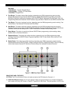
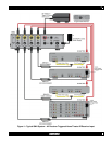
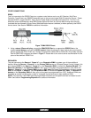
Other Applications
Using the same basic scheme described above, there are many options as to what device will be the System
Reference Device. In some cases it will be most intuitive to have a TV, Video Monitor or projector be the System
Reference Device. (See Figure 5 in this manual and the ISM4 Quick Start Guide for configuration and
programming instructions) Any time the TV is turned ON, by incorporating a SMVID01 Video Sensor on a TV
Video Output, the ISM4 will execute ON Macros to turn ON an A/V Receiver, DVD Player, Cable Box and Satellite
Receiver, for example. Another possibility would be to have a Video Game trigger the system. By making the
Video Game the System Reference Device, any time the Video Game is turned ON, the ISM4 will activate and
sync all appropriate devices for extreme gaming. The possibilities are endless. When incorporating an ISM4 into a
system, ask the question: “What device or appliance do I want to use to trigger other devices or appliances?”