ISM4 INSTALLATION & PROGRAMMING MANUAL
6
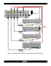
IR Receiver and receives IR signals from the receiver. IR signals input on this jack can control the ISM4 and
pass through to control the individual sources via the Source 1-4 IR Outputs.
12. IR Control. One 2-circuit (mono) 3.5mm mini jack connects to a normal Emitter Output on an IR repeater
system or IR Output on a system controller or A/V Receiver. IR signals input on this jack can control the ISM4
and pass through to control the individual sources via the Source 1-4 IR Outputs.
13. Power. 2.1mm coaxial jack connects to the included 12VDC 0.5A Power Supply (Xantech Part No
781ERGPS).
14. Expansion. One, 2-circuit (mono) 3.5mm mini jack connects to the Source 1 “Sense In” on a secondary ISM4
for system sync of three additional devices. When the Source 1 “Sense In” on the Primary ISM4 senses an
ON state (12VDC), this jack outputs 12VDC to the Source 1 “Sense In” on the Secondary ISM4 to indicate the
system ON state. The Source 2-4 devices on the Secondary ISM4 will then sync to the system as
programmed (turn ON). When the Source 1 “Sense In” on the Primary ISM4 senses an OFF state (0VDC),
this jack outputs 0VDC to the Source 1 “Sense In” on the Secondary ISM4 to indicate the system OFF state.
The Source 2-4 devices on the Secondary ISM4 will then sync to the system as programmed (turn OFF).
15. RS232. One, 3-circuit (stereo) mini jack connects to the RS232 Output on a system control device such as an
A/V Receiver, Whole House System Controller, etc. RS232 Commands Input on this port can trigger ISM4 IR
output for Source 1 Power (discrete ON/OFF, toggle ON/OFF) as well as Query Source Power State and
System info. This Port is bi-directional and will automatically send ISM4 System Status Info (Provided
Automatic Source Power State Notifications are enabled. Refer to the RS232 Control and Programming
section) when any Source state change has occurred or when queried by the RS232 control device.
16. Sense In. Four, 3-circuit (stereo) 3.5mm mini jacks connect to any of the Xantech SM Series Sensor
Modules. The ON/OFF state for each of Sources 1-4 will be detected by a Sensor Module appropriate for that
device, (i.e. SMVID01 Video Sensor for a DVD Player, SMVLT01 Voltage Sensor for a device with a 12V AC
or DC output such as an A/V Receiver or Whole-House System Controller). Each "Sense In" Jack is
associated with two IR Macros (ON/OFF) and a Source IR Output.
Before proceeding with this discussion, it is important to note that the Programming Procedure
imposes a requirement on the Source 1 (System Reference Device) macros that it does not impose on
any other macros. The requirement is as follows; on either the ON or the OFF Macros, the ISM4
assumes that the IR content (if programmed) of the first Command Structure (refer to the COMMAND
STRUCTURES section for a thorough description of Command Structures) be a Power Command. It
is left up to the programmer to ensure that this rule is strictly abided by. The problem is as follows; if
the System Reference device is manually (or by Remote Control) turned on, the resulting transition on
the System Reference Sense Input would be an Off-to-On transition. As a result, the ON Macro would
be launched. Given that a Toggle Power command is present in the macro, the Reference device
would immediately be turned off. Therefore, Toggle commands would not be permissible. The
programmer would be limited to discrete type of Power IR ONLY. Unfortunately, Discrete IR
commands are not as common as Toggle commands. To avoid this difficulty, the requirement stated
above was imposed. For any “Sense In” transition detected by the ISM4 on the Source 1 (System
Reference Input), the IR Content of the first Command Structure (containing a Power Command) will
be bypassed. If a Delay is programmed, however, it will be processed. The end result is that
regardless of whether or not a Toggle or a Discrete Power Command is present, the undesirable
situation described above would not take place. Hence, the more prevalent Toggle Power commands
can be utilized without any adverse effects at all. Please note that the IR content of Command
Structure 1 is only bypassed during execution of a “Sense In” initiated macro on the Source 1
(System Reference) Input. On every other case, the full macro will be executed. For instance, if the
trigger is a “Discrete Power On” RS232 (or IR) command, the entire macro would be executed. As a
result, having executed the first Command Structure, the System Reference Device will be turned on
as desired.


