


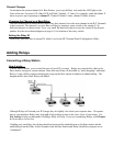

Because relay cabling is often troublesome, we supply a test cable for isolating the user-made cable from the
process. This test cable is so short that it doesn’t follow the rules of twists on the previous page – it is just a
Ethernet patch cable for node, but adequate for testing the relay.
HINT: Use the suggested wire type, and if you’re doing your own crimping, be sure to use the expensive metal
crimpers ($100) and not the cheap plastic crimpers ($15). Get someone familiar with making network (Ethernet)
cables, but be sure to tell them not to use the Ethernet pin outs for the Relay Stations, (it has been tried more
than once!).
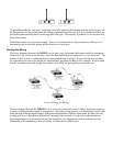
Testing the Relay
To test communication with a Relay, first check out the radio by doing a Site Test on the offending Relay
with all other Relays and Bases OFF. To check if a Relay is working with a Base Station, set the Base to a
different channel than the Relay and set the Terminal channel to match the Relay channel. Then cable-
connect the Relay to the Base (unlabeled port to unlabeled port.
Start your application on the host or use one of our demo programs provided with the Terminal (it’s a good
way to test) - it takes 10 or more seconds for the Terminal to switch to the Relay. The delay is a result of the
Terminal having to put out a "who can hear me" message when it doesn't get a response from the Base
Station. The Relay responds to the Terminals "who can hear me" message and communication is established
through the Relay. You will notice slightly slower throughput when working through the Relay.
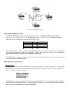
Relay ID and Channel…
Relays should be set to the same channel as the Base station and R/F Terminals that you will be using in your
system. Determining the current channel is the same as on the Base station; power up the Relay and count the
number of times the LED flashes (channel + 3). The default setting is channel 0 (3 flashes). Each Relay also
requires a unique Relay ID; the default ID is 0. A Relay will blink yellow; a Base blinks green.
Changing a Relay back to a Base
You can convert the Relay back to a Base Station by setting the Base/Relay jumper to the Base position. You
can check the outcome by simply powering up the unit - a Base blinks green; a Relay blinks yellow.
Changing the Channel on a Relay
The Relay must have their channel set to the same channel as the R/F Terminals in their network. The
channel is set on a Relay by turning a rotary switch to the setting 0-5. Use a very small flat head
screwdriver to turn the switch to the desired number.
Setting the Relay ID
If you only have one relay, there is no need to set the Relay ID which is shipped default as relay 1. If you
need to change it or you have multiple relays, it must be changed using the RF 700 Base Serial
Configuration Utility.
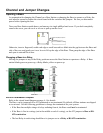
RS-422 Termination
When adding Relays to a system, the last Relay(s) in the line(s) must be terminated. By default, all Base
stations are shipped as terminated. Use the following guidelines to change the termination for your system:
Refer to the circuit board diagram on the previous page for details.
• If the Base has multiple strings of relays radiating from it, the Base would not be terminated but each
Relay would.