


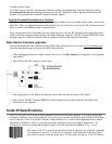

Incorrect Routing for Wiring
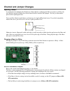
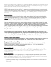
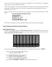
Relay Station RS422 Pin-outs
The R/F Relay Stations are connected by twisted pair wire -- use Belden 1227A1, Cat 5 wire, or
equivalent. The Unlabeled Port on the Base Station and the Unlabeled Port on the Relay Station are
connected with a straight cable using the following pin-outs:
Base Connector Pin # Relay Connector
Receive Data + 5 Transmit Data +
Receive Data - 6 Transmit Data -
Transmit Data + 2 Receive Data +
Transmit Data - 3 Receive Data -
Make a cable with 5-5, 6-6, 2-2, and 3-3 (a straight cable); but, be careful that you select wires so that the 2
wire is in the twisted pair with the 3 wire, and the 5 wire is in the twisted pair with the 6 wire. Do not use
pre-terminated Ethernet cables since the pairing is different.
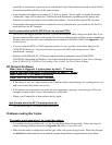
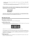
For all RJ Cable pin numbers, number from left to right with the metal pin side of the connector facing you and
the cable running to the down position
Relay Test Plan and Failures
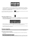
Relay Failure
Relay Station failures are often cable-related. If a Terminal puts out a “Who Can Hear Me?” message and a
Relay that is for some reason not connected to the Base Station (bad cable, cut cable, broken connectors)
hears it, it answers with the message:
Relay n Cannot Be
Heard by the Base
Notify Supervisor
Press Any Key
At this point, it is up to the operator to notify someone that the Relay is not communicating with the Base
and to check the cabling first. There is no message sent to the host, so it is very important that the operator
that receives this message notify someone immediately.