


Channel Changes
To determine the current channel of a Base Station , power up the Base and watch the LED light on the
front of the unit. On power UP, a Base LED will blink "channel +3" times. For example, a unit that blinks 5
times on power up is operating on channel 2. Channel 0 blinks 3 times, channel 5 blinks 8 times.
Changing the Channel on a Base/Relay
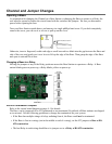
The Base Station and its related Relays must have their channel set to the same channel as the R/F Terminals
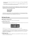
in their network. The channel is set on a Base or Relay by turning a rotary switch to the setting 0-5 (6
different channels to choose from). Use a very small flat head screwdriver to turn the switch to the desired
number. See the circuit board diagram on page A-1 for location of the rotary switch.
Setting the Relay ID
Each Relay must also have a unique ID, which is set by the RF Terminal Serial Configuration Utility.
Adding Relays
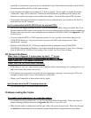
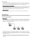
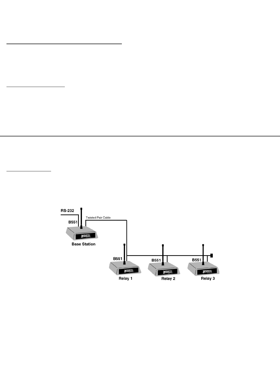
Connecting a Relay Station
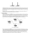
How it works…
A Relay station allows you to extend the area of your R/F coverage. Relays are connected by cable to the
Base station, acting as a remote antenna. More than one Relay can be added by “multi-dropping” additional
Relays. Using a Relay requires changing the setup on the Base station in addition to added cabling. The
diagram below shows how Relays are added:
Although Relays will extend your R/F range, they do slightly slow down your response time. If response
time is your problem, Relays may help only if the problem occurs on the outer limits of your range. Use
Site Testing to help you determine if adding a Relay will help. If you are considering Relays, read Chapter
4; Performance Issues first.
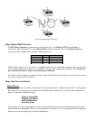
If adding only one Relay, the cabling should run between the unlabeled port on the Base station and the
unlabeled port on the Relay. In this example, both the Base Station and Relay should have jumpers set to
“terminated”.