


2−1
2 Audio Data Formats
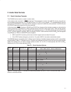
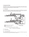
2.1 Serial Interface Formats
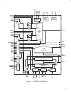
The TAS3002 device works in master or slave mode.
In the master mode, terminal 21 (IFM/S
) is tied high. This activates the master clock (MCLK) circuitry. A crystal can
be connected across terminals 13 (XTALI/MCLK) and 14 (XTALO), or an external, TTL-compatible MCLK can be
connected to XTALI/MCLK. In that case, MCLK is outputs on terminal 12 (MCLKO), with terminals 19 (LRCLK/O) and
20 (SCLK/O) becoming outputs to drive slave devices.
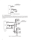
In the slave mode, IFM/S
is tied low. LRCLK/O and SCLK/O are inputs and the interface operates as a slave device
requiring externally supplied MCLK, LRCLK (left/right clock), and SCLK (shift clock) inputs. There are two options
for selecting the clock rates. If the 512f
S
MCLK rate is selected, terminal 11 (CLKSEL) is tied high and an MCLK rate
of 512f
S
must be supplied. If the 256f
S
MCLK is selected, CLKSEL is tied low and an MCLK of 256f
S
must be supplied.
In both cases, an LRCLK of 64SCLK must be supplied.
• MCLK and SCLK must be synchronous and their edges must be at least 3 ns apart.
• If the LRCLK phase changes by more than 10 cycles ofMCLK, the codec automatically resets.
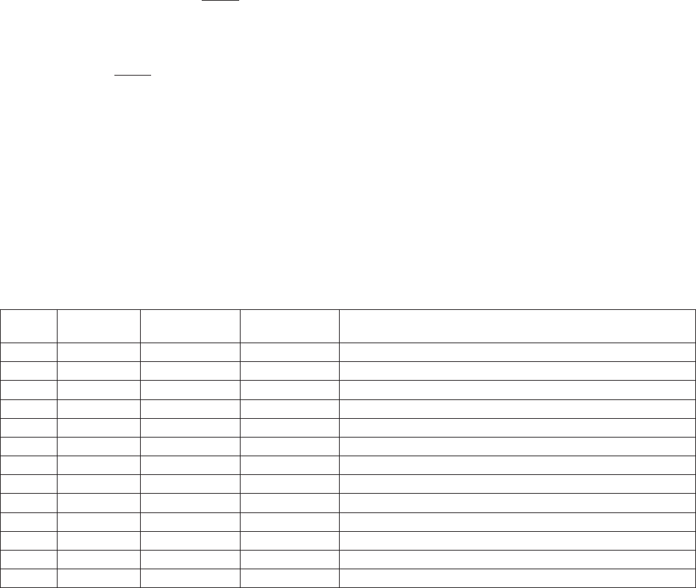
The TAS3002 device is compatible with 13 different serial interfaces. Available interface options are I
2
S, right justified,
and left justified. Table 2−1 indicates how the 13 options are selected using the I
2
C bus and the main control register
(MCR, I
2
C address 01h). All serial interface options at either 16, 18, 20, or 24 bits operate with SCLK at 64f
S
.
Additionally, the 16-bit mode operates at 32f
S
.
Table 2−1. Serial Interface Options
MODE MCR BIT (6) MCR BIT (5−4) MCR BIT (1−0)
SERIAL INTERFACE
SDIN1, SDIN2, SDOUT1, SDOUT2, AND SDOUT0
0 0 00 00 16-bit, 32f
S
1 1 00 00 16-bit, left justified, 64f
S
2 1 01 00 16-bit, right justified, 64f
S
3 1 10 00 16-bit, I
2
S, 64f
S
4 1 00 01 18-bit, left justified, 64f
S
5 1 01 01 18-bit, right justified, 64f
S
6 1 10 01 18-bit, I
2
S, 64f
S
7 1 00 10 20-bit, left justified, 64f
S
8 1 01 10 20-bit, right justified, 64f
S
9 1 10 10 20-bit, I
2
S, 64f
S
10 1 00 11 24-bit, left justified, 64f
S
11 1 01 11 24-bit, right justified, 64f
S
12 1 10 11 24-bit, I
2
S, 64f
S
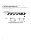
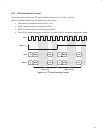
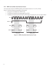
Figure 2−1 through Figure 2−3 illustrate the relationship between the SCLK, LRCLK, and the serial data I/O for the
different interface protocols.