


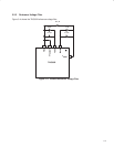


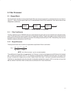

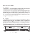
4−7
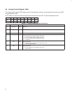
4.12 Main Control Register 1 (01h)
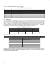
The TAS3002 device contains two main control registers: main control register 1 (MCR1) and main control register 2
(MCR2). The MCR1 register contains the bits associated with load speed, SCLK frequency, serial-port mode, and
serial-port word length. It is accessed via I
2
C with the address 01h.
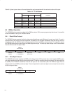
MCR1 (01h)
Bit b7 b6 b5 b4 b3 b2 b1 b0
Type R/W R/W R/W R/W R R R/W R/W
Default 1 X X X X X X X
Table 4−2. Main Control Register 1 Description
BIT
FIELD NAME
TYPE DESCRIPTION
7 FL R/W Fast load
0 = Normal operation mode
1 = Fast -load mode (default)
6 SC R/W SCLK frequency
0 = SCLK is 32 f
S
.
1 = SCLK is 64 f
S
.
5−4 E R/W Serial port mode
00 = Left justified
01 = Right justified
10 = I
2
S
11 = Reserved
3−2 Reserved R Reserved
1−0 W R/W Serial port word length
00 = 16-bit
01 = 18-bit
10 = 20-bit
11 = 24-bit
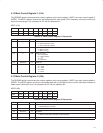
4.13 Main Control Register 2 (43h)
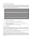
The TAS3002 device contains two main control registers: main control register 1 (MCR1) and main control register 2
(MCR2). The MCR2 register contains the bits associated with the AllPass function and the download of bass and
treble control information, and it is accessed via I
2
C with the address 43h.
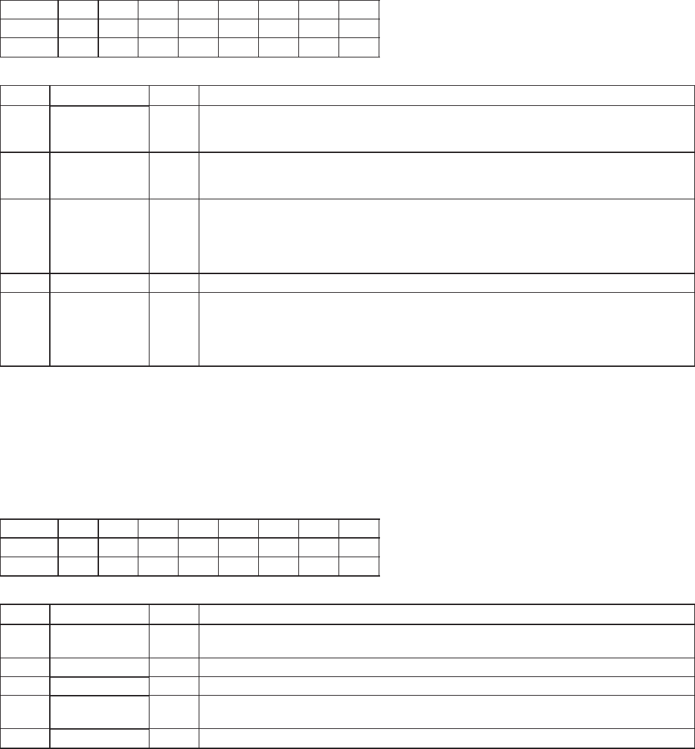
MCR2 (43h)
Bit 7 6 5 4 3 2 1 0
Type R/W R R R R R R/W R
Default 0 0 0 x x x 0 0
Table 4−3. Main Control Register 2 Description
BIT
FIELD NAME
TYPE DESCRIPTION
7 Reserved R/W 0 = Normal operation (initial condition after reset)
1 = Download bass and treble
6−5 Reserved R Reserved. Bits 6 and 5 return 0s when read.
4−2 Reserved R Undefined.
1 DM(1−0) R/W 0 = Normal operation (initial condition after reset)
1 = AllPass mode (bass and treble are still functional)
0 INP R Reserved. Bit 0 returns 0 when read.