


8−3
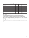
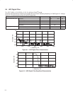
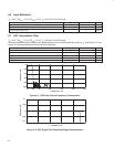
0.002
−0.002
Amplitude − dB
0.004
0.006
0.008
0
0
f − Frequency − Hz
0.1 f
s
0.2 f
s
0.3 f
s
0.4 f
s
0.5 f
s
Figure 8−3. ADC Digital Filter Pass-Band Characteristics
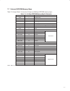
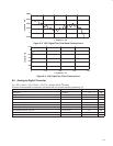
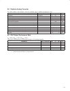
−0.4
−1
Amplitude − dB
−0.2
0
0.2
−0.6
−0.8
0
f − Frequency − Hz
1 f
s
2 f
s
3 f
s
4 f
s
Figure 8−4. ADC High-Pass Filter Characteristics
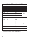
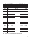
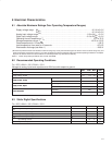
8.5 Analog-to-Digital Converter
T
A
= 25°C, AV
DD
= 3.3 V, DV
DD
= 3.3 V, f
S
= 48 kHz, 20-bit I
2
S mode
All terms characterized by frequency are scaled with the chosen sampling frequency, f
S
.
PARAMETER TEST CONDITIONS MIN TYP MAX UNIT
SNR (EIAJ) A weighted 93 dB
Dynamic range −60 dB, 1 kHz 88 dB
Signal to (noise + distortion) ratio −1 dB, 1 kHz, 20 Hz to 20 kHz 82 dB
Power supply rejection ratio 1 kHz (see Note 3) 50 dB
Idle channel tone rejection +110 dB
Intermodulation distortion −80 dB
ADC crosstalk −93 dB
Overall ADC frequency response 20 Hz to 20 kHz ±0.1 dB
Gain error 5%
Gain matching ±0.02 dB
NOTE 3: Measured with a 50-mV peak sine curve.