


4−6
4.10 Dynamic Range Compression/Expansion (DRCE)
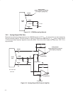
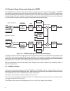
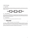
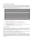
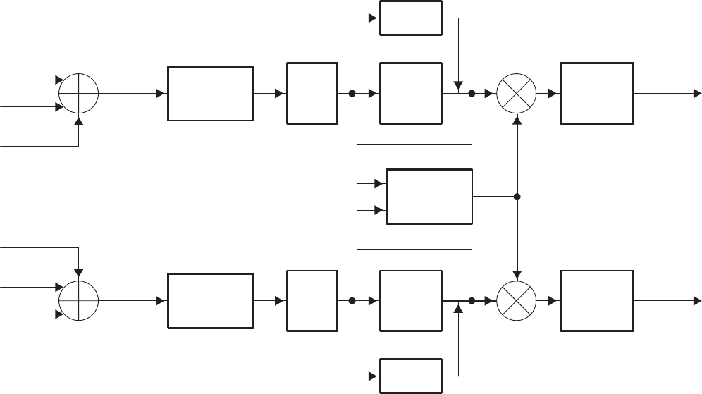
The TAS3002 device provides the user with the ability to manage the dynamic range of the audio system. The DRCE
receives data, and affects scaling after the volume/loudness block. As shown in Figure 4−4, the DRCE is applied after
the volume/loudness control block as a DRCE scale factor. The DRCE must be adjusted such that the signal does
not reach the hard limit value. However, if the signal does reach the maximum digital value, the saturation logic serves
as a hard limiter that does not allow the signal to extend beyond the available range.
SDIN2_L
(7)
2
nd
Order
IIR Filters
Bass/
Treble
Soft
Volume/
LEFT_OUT
Loudness
(Parametric
Equalization)
(Tone)
LEFT_SUM
SDIN1_L
(Left Channel Mixer)
ANALOGIN_L
(DRCE Scaling)
Saturation
Logic
Dynamic
Range
Control
(
Analog in From ADC)
SDIN2_R
(7)
2
nd
Order
IIR Filters
Bass/
Treble
Soft
Volume/
RIGHT_OU
T
Loudness
(Parametric
Equalization)
(Tone)
RIGHT_SUM
SDIN1_R
(Right Channel Mixer)
ANALOGIN_R
(DRCE Scaling)
Saturation
Logic
Figure 4−4. TAS3002 Digital Signal Processing Block Diagram
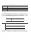
The DRCE instruction consists of eight bytes that must be sent each time in the order shown in the example code
of NO TAG. Each instruction downloaded must be eight bytes. If only one byte is changed, all eight bytes must be
transmitted. The first two bytes remain the same for every instruction, however the last six bytes can be programmed
using hexadecimal values from the corresponding tables referred to in Section NO TAG.
With high compression ratios and fast attack times available, this function is suited for a commercial killer in a
television set application.
4.11 AllPass Function
This function is enabled by setting terminal 27 (ALLPASS) on the TAS3002 device to 1. When asserted, the internal
equalization filters are set into AllPass (flat) mode. When this terminal is reset to 0, the equalization filters are returned
to the equalization that was in use before the terminal was asserted.
In AllPass mode, the bass and treble controls are still functional.
This function is frequently used for headphones. When the headphone plug is inserted into its jack, a switched contact
in the jack enables the AllPass function.
The AllPass function also can be activated by writing a 1 to bit 2 of the analog control register.