


8−6
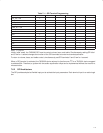
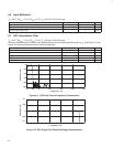
8.10 I
2
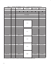
C Serial Port Timing Characteristics
MIN MAX UNIT
f
(SCL)
SCL clock frequency 0 100 kHz
t
(buf)
Bus free time between start and stop 4.7 µs
t
(low)
Low period of SCL clock 4.7 µs
t
(high)
High period of SCL clock 4.0 µs
t
h(sta)
Hold time repeated start 4.0 µs
t
su(sta)
Setup time repeated start 4.7 20 µs
t
h(dat)
Data hold time (See Note 6) 0 µs
t
su(dat)
Data setup time 250 ns
t
r
Rise time for SDA and SCL 1000 ns
t
f
Fall time for SDA and SCL 300 ns
t
su(sto)
Setup time for stop condition 4.0 µs
C
(b)
Capacitive load for each bus line 400 pF
NOTE 6: A device must internally provide a hold time of at least 300 ns for the SDA signal to bridge the undefined region of the falling edge of
SCL.
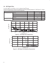
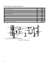
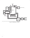
SDA
PS
Valid
Change
of Data
Allowed
P
SCL
t
(buf)
t
h(sta)
t
r
t
h(dat)
t
f
t
h(sta)
t
su(dat)
t
su(sta)
t
su(sto)
Data
Line
Stable
NOTE: t
(low)
is measured from the end of t
f
to the beginning of t
r
.
t
(high)
is measured from the end of t
r
to the beginning of t
f
.
Figure 8−7. I
2
C Bus Timing